

Computer Networks
 Created Created | |
|---|---|
 Contact Contact | pranav.joshi@iitgn.ac.in |
 Creator Creator | Pranav Joshi |
Chapter 1
What is the Internet ?
Two ways of answering
- nuts and bolts : hardware and software components that make up the internet
- Networking infrastructure : provides service to distributed applications
early internet devices
- PC
- Linux workstations
- servers
modern internet devices
- laptops
- smartphones
- tablets
- etc..
hosts / end systems
ALL of the devices listed above are labelled “hosts” or “end systems”
- In 2015, there were hosts, which is 40% of world population at that time
- End systems are linked by communication links and packet switches .
communication links can be made of
- coaxial cable
- copper wire
- optical fibre
- radio spectrum
- transmission rate of a link is measured in bits/second
Simplified Transmission Process
When the sending end system A has to send information to the receiving end system B, these operations are performed by A :
- segment the data
- adds header bytes to each segment
- Each segment is now a packet .
The packets are reassembled into the original data at B.
Packet switch
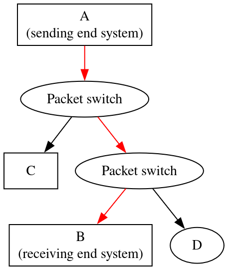
A packet switch takes the information coming from one end and forwards it to the correct outgoing communication link , out of the many that it handles.
major types of packet switches
- routers (used in network core)
- link-layer switches (used in access networks)
route / path
it’s the sequence of communication links and packet switches traversed by a packet from the sending end system A to the receiving end system B.
dot code
digraph G {
    rankdir=TD;
    A [label="A\n(sending end system)",shape=box]
    B [label="B\n(receiving end system)",shape=box]
    C [shape=box]
    P1 [label="Packet switch"]
    P2 [label="Packet switch"]
    A -> P1 [color=red]
    P1 -> P2 [color=red]
    P1 -> C
    P2 -> B [color=red]
    P2 -> D
}
ISP
- End systems access the internet through Internet Service Providers (ISP)
An ISP can be ..
- residential ISPs
- local cable
- telephone companies
- corporate ISPs
- University ISPs
- ISPs that provide Wifi
- cellular data ISPs, providing mobile data access
- residential ISPs
- Each ISP is a network of packet switches and communication links
- Low level ISPs are connected to (national and international) upper-tier ISPs such as :
- Level 3 communications
- AT&T
- Sprint
- NTT
- Upper level ISPs are interconnected through high speed fiber-optic links
- Each ISP is managed independetly
TCP/IP
- ISPs run the IP protocol
This protocol determines the format of the packets sent and recieved among routers (types of packet switches) and end systems
- end systems run the TCP protocol
- ISPs run the IP protocol
Internet standards
- Since the internet runs on protocols, standardisation is important.
- Internet Engineering Task Force (IETF) (no kidding, this is really the name) creates these standards, called “requests for comments” or RFCs in short.
- RFCs were initially just general requests for ..comments (very original ..) to resolve the protocol design issues faced by the precursor to the internet.
- RFCs are quite detailed
- RFCs define protocols such as :
- TCP (hosts)
- IP (ISPs)
- HTTP (web)
- SMTP (mail)
- The IEEE LAN/MAN standards committe (not IEFT) specifies the Ethernet and WiFi standards.
Services Description
The description so far describes the parts (nuts and bolts) that make the internet (as an entity).
The other way is to think all of internet as a giant tool, an infrastructure used for providing services to applications, such as …
Long list of applications
- Web surfing
- messaging
- mapping, with real-time road-traffic information
- music/movie/media streaming from cloud
- social networks
- video conferencing
- real-time multi-person games
- location-based recommendation systems
Each of these applications are said to be distributed applications since the full application runs on all the hosts combined, not just on one machine.
This is also why we call the end systems as “hosts” , since they effectively host any application.
Sockets
End systems provide a socket interface that specifies how a program running on an end system A asks the internet infrastructure to deliver to a specific destination program running on end system B.
A socket is analogous to a postbox in a postal service. To get a letter delivered, you don’t just send the data, on demand. Instead, you envelope it, put addresses on it, stamps, and other things, and put it in the post box. Then the next day, it’s mAgIcaLLy (sarcasm) already in the system for the postal service.
Moreover, just as a postal service provides more than one service (just letters), such as delivering parcels, reception confirmation, etc. ; in a similar manner, the internet infrastructure can do a lot of things
Protocol Definition
A protocol defines the format and the order of messages exchanged between two or more communicating entities, as well as the actions taken on the transmission and/or receipt of a message or other event.
Protocol Example : Opening a link to a web page
- First, your host (laptop, smartphone, whatever) sends a communication request to the Web server.
- Second, the web server with reply with either an OK , or a repectful way of saying “~ yamete kudasai ~”. If you recieve the second response, most you can do is get frustrated and curse your luck, since no means no.
- After getting (hopefuly) an OK response, you try to GET it (it, being the Web-page’s HTML or XML) , by sending the name (URL) of the Web-page to fetch, in a GET message.
- In response, the Web server serves it you (it, being the Web-page’s HTML or XML) …… like a bi-
- Moving on to the Network Edge .
The Network Edge
What’s edge ?
It’s not the browser, nor the trick you use to prolong a certain other process….
End systems are the one that sit at the edge of the internet, since they are leaf nodes for the massive tree than the internet is.
IOT
The “internet of things” is a concept where everything that can possibly be connected to the internet is connected. EVERYTHING, including toilets, glasses, watches, dolls, whatever you want.
It’s like R34 but worse, since with R34 only what is on the internet can be ruined (or improved, whatever you prefer..asking for a friend), but with this, EVERYTHING can be ruined.
Imagine some guy remotely accessing your toilet and opening all the doors while you’re doing your deed . Not fun.
DSL
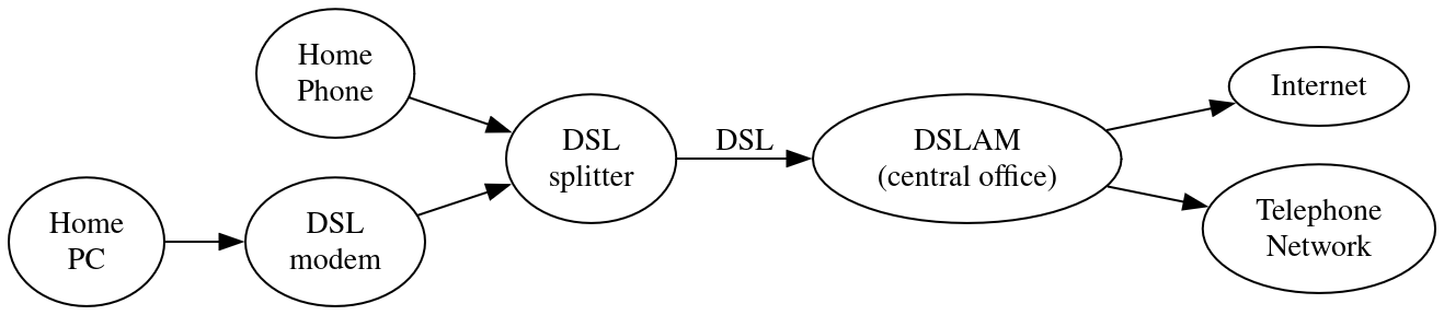
A Digital Subscriber Link is a way to provide wired access to both the internet and the telephone network through one cable.
dot code
digraph G {
    rankdir= LR
    "Home\nPhone" -> "DSL\nsplitter"
    "Home\nPC" -> "DSL\nmodem"
    "DSL\nmodem" -> "DSL\nsplitter"
    DSLAM [label="DSLAM\n(central office)"]
    "DSL\nsplitter" -> DSLAM [label="DSL"]
    DSLAM -> "Internet"
    DSLAM -> "Telephone\nNetwork"
}
Here,
DSL modem
This is a device that connects either the Ethernet router, Wifi router, or directly a single end system to the DSL network.
A “MoDeM” is something that Modulates and De-Modulates data. In particular, the digital data from a computer is modulated using analog signals.
There are various ways of doing it.
DSL spitter
This is a low pass analog low-pass filter that reduces the interference of higher frequency noise from the telephone . It combines the signals from the modem and the telephone by simple superposition.
DSL cable
It carries signals in 3 frequency regimes :
- low frequency (0-4kH) telephone signals
- moderate frequency (4-50 kH) upstream data (uploading files, for example)
- high frequency (50kH - 1MH) downstream data (downloading, streaming, etc.)
Since the upstream and downstream transmission rates are asymmetric, so we call this “ADSL” , while one with symmetric rates is just “DSL”, no prefix.
DSL is for short distances (5 to 10 miles) . If a residence is farther than that from the central office (CO) of the telcom (where the DSLAM is located) , then the residence must resort to some other way of internet access.
DSLAM
- This first separates the signals based on frequency domains
- Then, it does analog to digital conversion
- The “AM” part in DSLAM stands for “Access Multiplexer”, that is to say, it’s main function is to multiplex (choose) the packets to send to the internet or the signal to send to the telephone lines from the thousands of DSL lines connected to it.
The actual transmission rates for the customer may be lower than the theoretical rate, when tiered services are offered.
Cable Internet access
What is it ?
Just like how DSL uses a telco’s existing telephone insfrastructure to also provide internet access, similarly, a cable TV company’s infrastructure can be used to provide internet access as well.
HFC
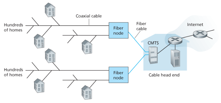
Hybrid Fiber Coax access networks are usually used for cable TV connection. It’s called so, since it uses both optical fibre for the long range connection, and coaxial metal cables for the many short range ones.
Notice that in DSL, even if there was involvement of fiber optics to connect to the internet from the CO (and there was not), the access network uses only coaxial cables. Thus DSL is not an HFC.
Fiber node
These are neighbour-hood level junctions, connected to the CMTS via optical fibre cables.
Meanwile the individual houses are connected to the fiber node via coaxial metal cables.
Cable modems
Just like a DSL model, cable internet access require cable modems. This is an external device that connects to the home PC through an ethernet port.
CMTS
The cable modem termination system is similar to DSLAM. It does ADC and it divides the HFC network into 2 channels; upstream, and downstream.
The downstream channel usually uses higher frequencies.
Shared boadcast
Cable access network doesn’t have a multiplexer system, as you can see.
This is because it’s actually a shared broadcast system, i.e. the packets are sent to the full neighbourhood, not just a single house.
To avoid collisions of access requests and other messages, a “Distribute Multiple Access Protocol” is needed.
Plus, if multiple ppl are downloading a file on the downstream channel, the actual rate will be much lower.
FTTH
- DSL and cable networks make up 85% of residential broadband access in US (at that time)
- An “up-coming” (at that time) technology in fibre to the home (FTTH).
Direct Fibre
It’s just DSL, except they provide an optical fibre path from the CO directly to the home.
AON
“Active Optical Network is essentially switched Ethernet”
Yeah sure.. explains a lot .. this asshole author ..
PON
- A Passive Optical Network is used by Verizon’s FIOS service
ONT
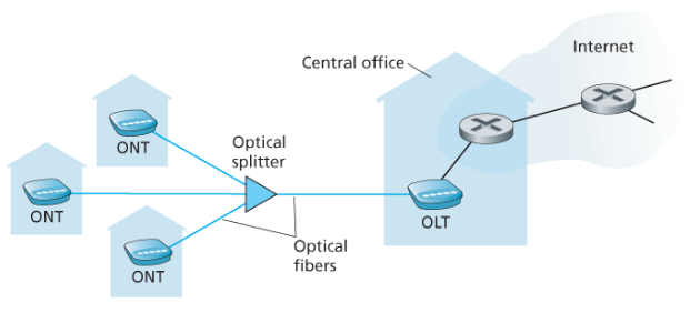
Each home has an Optical Network Terminator, which is connected to the optical splitter.
In turn, the home router (typically wireless) is connected to the ONT. The residents actually access the internet using this home router.
The ONT receives all the data transmitted by the OLT, similar to cable network. The ONT only picks up data packets that it should.
Optical splitter
This combines less than 100 fibres into a single fibre which connects to the OLT
For PON, this device is passive.
Basically, it needs no power, and does no computation of its own.
Instead, the splitter just forwards the packets recieved to every ONT it is connected to, similar to what happens for cable.
Thus, encryption.
OLT
The Optical Line Terminator is located in the telco’s CO.
This converts between optical and electrical signals, and connects to the internet via a telco. router
Comparison
Although the theoretical rate for FTTH can be in Gbps, the average downstream rate in 2011, US was 20 Mbps, while that for DSL was just 5 Mbps, and for cable TV, 13 Mbps
This is of course out-dated. My internet speed is 100 Mbps downstream and 65 Mbps upstream, at the time I’m writing it. Makes you wonder if this book is even relevant…
Satellite link
In rural areas where it might not be possible for cables and fibres to reach, low speed (1Mbps) internet can be provided by a satellite link.
A satellite link uses signals in the satellite radio spectrum for sending packets.
StartBand and HughesNet are two satelite access providers
Dial-Up
This is the worst thing ever. It used to provide only 56 kbps , much lower than any other access network.
It uses the same infrastrcture as DSL. There’s a home modem that connects over a phone line to a modem in the ISP.
The difference is the modulation happens very inefficiently and in the same frequency range that the telephone line uses, while DSL in comparison uses much high frequencies.
Ethernet
Ethernet switch
This is a packet switch that serves many computers or other Ethernet switches, from the same Ethernet coaxial cable.
Institutional router
Similar to a WiFi router, this connects to all the Ethernet switches or end-systems in a local area, and performs the operation of “routing”
This router is connected to the institution’s ISP.
Speed
Ethernet and other LANs are fast. The transmission rate reaches 100Mbps just like that.. sometimes even 1 Gbps
Meanwhile, the institutional servers operate on Gbps .
WiFi
Wireless LAN access based on IEEE 802.11 technology, a.k.a. WiFi is everywhere around us.
Wireless users transmit packets to-and-from a WiFi access point, which is usually connected to a wired Ethernet, which in turn is connected to the (wired) Internet.
Cellular Data
Mobile data runs on the same principle as WiFi.
The mobile data towers are the access points, and the smartphones/tables are the hosts.
To use mobile data, you only need to be within a few tens of kilometers close to the base station, as opposed to few tens of meters for a WiFi access point.
This comes with a catch. The transmission speed is rather low, with a theoretical maximum of 20Mbps of average, with 5G. With 3G, it’s just 1Mbps.
Long Term Evolution technology, a.k.a. LTE is based on 3G, and can achieve rates in excess of 10Mbps (with 3G) .
It’s as they say .. mobile “phone” .. , not mobile “computer” .
Wifi vs Cellular
Feature Wi-Fi Cellular (e.g., 4G/5G) Uses radio spectrum? ✅ Yes ✅ Yes Frequency bands 2.4 GHz, 5 GHz, 6 GHz (unlicensed) Various (700 MHz to 3.5 GHz+), licensed Licensed spectrum? ❌ Unlicensed (open to everyone) ✅ Licensed (bought by telcos) Ownership You own/manage your Wi-Fi Telcos control the cellular network Range Short (tens of meters) Long (kilometers) Mobility support Low (mostly fixed usage) High (handoff between towers) Typical use Homes, cafes, offices Mobile broadband (phones, IoT)
Access network
Instead of just defining this vaguely at the start, now is a good time to define this.
An access network is the local network used by a group of end systems to “Access” the internet, hence the name.
The parts involved in the internet itself is what is called a Network Core.
link-layer switch
Examples we encountered
- Ethernet switch
- DSLAM
Non-examples we encountered
- FTTH optical splitter
Essentially, a link-layer switch forwards packets between devices on the same access network using the MAC address, not the IP address
Physical Media
Guided media
Here, the path that the packet physically takes is guided by some solid construct, such as :
- twisted copper wires
- fiber-optic cables
- coaxial cables
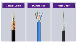
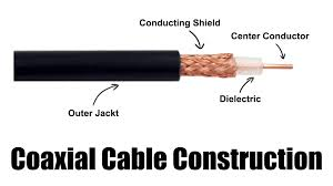
Unguided media
There is no “path” . The packet is transmitted to all of 3D space, decaying with the inverse square law.
So, it’s mostly low frequency (radio) waves. (Imagine devices radiating UV rays .. not fun, both for ppl and for cost)
Examples :
- Wifi
- satellite links
- cellular connection
Propagation time and transmission rate
While you may think that the length of the cables or distance that a radio spectrum packet has to travel is a factor (and yes, it is) , it’s usually the delays between the (modulated) bits maintained for reliable transfer of data that gives us the transmission rate.
The time to travel the medium, known as propagation time is usually tiny.
So, to transmit a packet of bits over a medium with transmission rate , you need time.
The Network Core
Store-and-forward packet switching
What routers usually do is that for a packet they are in the process of receiving, they store all the bits till the packet is complete and then forward it .
There is usually, no delay between the packets. The router must therefore queue the packets when they arrive.
The queue is called an output buffer/queue . There is one output buffer for each link that a router is attached to.
In case the output buffer of a link starts overflowing, either the arriving packet or one of the already queued packets will be dropped. This is given the very unoriginal name of “packet loss”
The delays due the packets waiting in the output queue are called (guess what) , the queuing delays .
Packet switching procedure
Every packet comes with a destination IP address attached to it.
When the router sees the packet, it extracts some portion of the address and uses a forwarding table to find which outbound (fancy word for out-going) link to forward the packet to.
Circuit links
This is what is used for telephone lines.
Each communication link is made of “circuits”, which are individual links.
Don’t be the deceived by the picture below. The circuits need not be wires or some physical medium. The picture is just for illustration.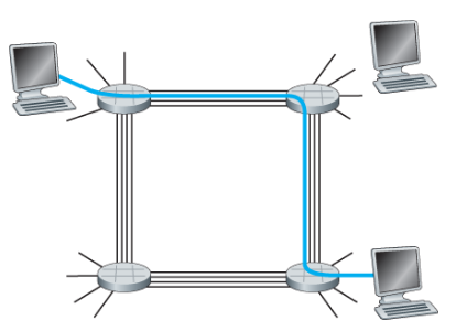
Unlike packet switch based communication, where even after a connection is established, you have to wait; in a circuit based system, the connection (a series of circuits) is maintained all the way until the termination. This of course means that the connection is “on-demand” , rather than on all the time, like for packet switches.
For each connection, from each link, there’s only 1 circuit.
FDM
Frequency division multiplexing is just individual signals, frequency modulated (FM) in different frequency bands, all sent through the same link. The width of the frequency bands is called.. guess it .. the bandwidth .
In telephone networks, the bandwidth is typically 4 kHz
FDM is in practice, a way to break a link into multiple links, a.k.a. circuits.
(Remember what I said about not being deceived by the picture?)
TDM
Time Division Multiplexing is a Round Robin scheme where each “circuit” gets its chance (slot) to transmit a bit each cycle (frame).
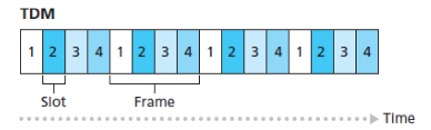
The transmission rate is then (obviously) the frame rate times the number of slots in a frame.
Packet Switch vs Circuit Switch
Packet switching is more efficient for the full network, while Circuit Switching is more reliable for real-time applications, such as phone calls.
The internet
Let’s start with this picture :
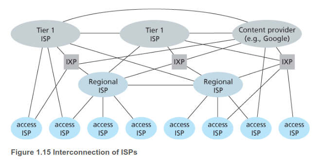
access ISP
These are the telcoms , universities, enterprise ISPs, etc. that create an access network for the customers.
These are like retail stores.
They get their high speed internet connection from the regional and tier 1 ISPs
Regional ISP
These provide internet access to the many access ISPs in a region. For example, China has a whole bunch of state-level and nation-level ISPs.
PoP
A Point of Presence is a router or a group of routers, all at the same location, belonging to a particular ISP. That is to say, it’s a point of that ISP’s presence.
Any lower (or similar) level ISP can connect to the said ISP at its PoPs
Tier 1 ISP
An ISP that doesn’t have to pay to some other ISP for access to their network is called a tier 1 ISP. These form the back-bone of the internet.
Peering
This is when two ISPs decide to connect their networks to each other directly, rather than connecting to some higher ISP for indirect access to each other’s networks.
This is usually settlement-free (free of charges for both ISPs) since both benefit.
IXP
And internet exchange point is a building where multiple ISPs peer with each other
Multi-home
Any ISP (except tier-1) can decide to connect to internet via multiple higher level ISPs.
This ensures that the ISP will function even if one of the higher level ISPs has a failure.
Content providers
Google has its own private network of data centers.
When you go to
www.google.com, you are most likely not going through some tier 1 ISP. Instead, your access ISP is probably peering with Google, either directly, or though an IXP.This is done for many reasons.
- Faster internet
- low long term cost for google
- Secure network, with no data leakage
- Control over the network: Google’s network won’t suffer from congestion on the public internet. Moreover, they can engineer their own optlimised routes.
Delay, Loss and Throughput for Packet-Switched Networks
Transmission delay
This is the amount of time take by a packet to leave a router.
Essentially, when the last bit of a packet is stored at a router, the first bit start to be transmitted by the router. So the distance that the first bit could have covered by the point that the last bit reaches is NOT covered, causing a delay. Suppose the packet is of bits and the theoretical (if the packets (not bits) had no delay between them) maximum transmission rate is (in bits/sec); then the transmission delay incurred to the full stream of packets due to a single store-and-forward type packet switch is
Propagation delay
This is the time needed for the first bit to go from on end of the link to the other end. This is simply where is the length of the link and is the speed of the wave in that medium.
Queuing delay
You can easily imagine that no matter how close the packets are, by the time the last bit of a packet reaches, the last bit of the earlier packet is already transmitted in case only a single incoming like is sending packets.
But there’s not just one link. Instead, multiple links can be sending packets to the router simultaneously. This is what the stupid book calls a “burst”.
In case packets arrive simultaneously, the packet to be transmitted out has a delay of , i.e. the transmission delays of packets sent before added up.
This extreme scenario is good as a worst-case scenario. But the real-life scene is more complicated.
Suppose the rate of arrival of packets (from all incoming links combined) is , then if , over time, the output buffer will overflow, making the delay go to .
If , the queueing delay is based on the nature of the incoming traffic. If it’s in an alternating fashion, there is no delay. If it’s in bursts, there’s a queuing delay of (at-most) is a particular incoming stream as we saw in the example, and the sum of delays is .
When the arrival times are more or less i.i.d.r.v, the average queuing delay is (theoretically) a monotonically increasing function of the traffic intensity .
There’s a whole theory around it… stats, yum.
Processing delay
The last source of delay is the delay due to processing done by the router to decide the output link.
Packet loss
When a packet arrives at a router and it founds that there’s not enough space in the output buffer, it is dropped.
Thus, even though we had assumed the queuing delay to be for a never ending stream of packets, it’s not actually infinite, since the packets that can’t be accommodated are just forgotten about, thus incurring no delay at all for them.
Thus, the two metrics that describe the performance of a packet switch are the delay and the probability of packet loss.
End system delay
Sometimes, the end systems themselves purposefuly delay the transmission of packets. For example, when the end system is sharing the medium with other end system (WiFi, cable modem)
Packetization delays
In some applications, such as Voice-over-IP (VoIP) , the sender end system much first fill the packet with encoded digitized speech before starting transmission. This can cause a delay.
End to end delay
Supposes there are links between the source and destination, and routers, then the delay is
This is oversimplified in the stupid book by assuming that even the end system causes the same transmission delay as the routers, and that the queuing delay is 0 everywhere, giving the over-estimate of
The reason it does this is so that the implementation of their “TraceRoute” program makes sense
TraceRoute
Unlike a normal system where the routers just forward to the correct link, in TraceRoute, a message is sent back to the incoming link as well (remember, a link is bi-directional, and simultaneous upstream and downstream can be handled)
The time delay between the message being transmitted and the response from the router coming back is approximately the same as the full round trip delay caused by that link in the actual process.
For accuracy, the whole thing is repeated 3 times (i.e. the sender sends packets, each packet designed for a specific router)
Throughput
Remember FAI:Multi-agent systems ?
Remember “flows” in “networks” .. it’s exactly the same here.
Suppose you have a very simple case of many links between source end system and destination , with transmission rates , then the end-to-end throughput (number of bits reaching per unit time, not just ones transmitted by ) is just .
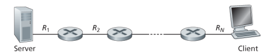
Note that the delays are irrelevant here, since they were for a particular packet, while this is for the full, steady stream of packets.
For a more general case, consider this :
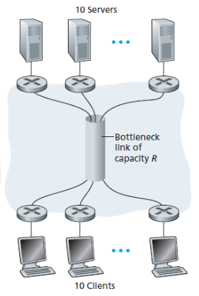
Although the full capacity is , in actuality, the rate for each sender-receiver pair (a circuit, if you will) is just (assuming symmetry).
You can now apply the theory learnt in FAI to find what’s the optimal flow, and what’s a fair flow.
Protocol Layers and Their Service Models
Application layer
HTTP
web document request and transfer
SMTP
Email message transfers
FTP
Transfer of files
DNS
The Domain Name System converts the human readable end system names to 32-bit network addresses
- Application layer packets are called “messages”
Transport Layer
TCP
- connection oriented service
- Guaranteed delivery of application-layer messages
- flow control (matching speeds of sender and reciever)
- Breaks long messages to shorter segments
- Provides congestion control mechanism so that the source throttles (limits) its transmission rate when network is congested.
UDP
- connectionless service
- No reliability, flow control, or congestion control
- Transport layer packets are called “segments”
Network layer
- Network layer packets are called “datagrams”
Overview
Given a transport layer segment and a destination address, provided by TCP of UDP, the network layer delivers the segment to the transport layer in the destination host
IP
This is the only important protocol that the network layer uses.
Although there are many routing protocols in this layer, IP is the glue that binds the network layer together
Link Layer
To move a datagram from one node (host or router) to the next node, “protocols” such as Ethernet, WiFi, PPP, and cable access network’s DOCSIS protocol are used.
Link layer packets are called “frames”
Physical layer
While link layer moves frames from one node to another, the physical layer moves the bits.
OSI
This is an out-dated 7 layer model, which has two extra layers right below the application layer
Presentation layer
- Data compression
- Data encryption
- Data description (converts the data from the host system’s format to a more standardised format)
Session layer
Delimits and synchronises the data exchange.
These facilities may not be necessarily be used in practice. It’s up to the application developer, and thus, in the modern internet layer architecture, this stuff is included as parts of the application layer itself.
Encapsulation
Idk why this thing is called “Encapsulation” but whatever.
Every layer breaks the packets from upper layer and adds extra header information ( ) .
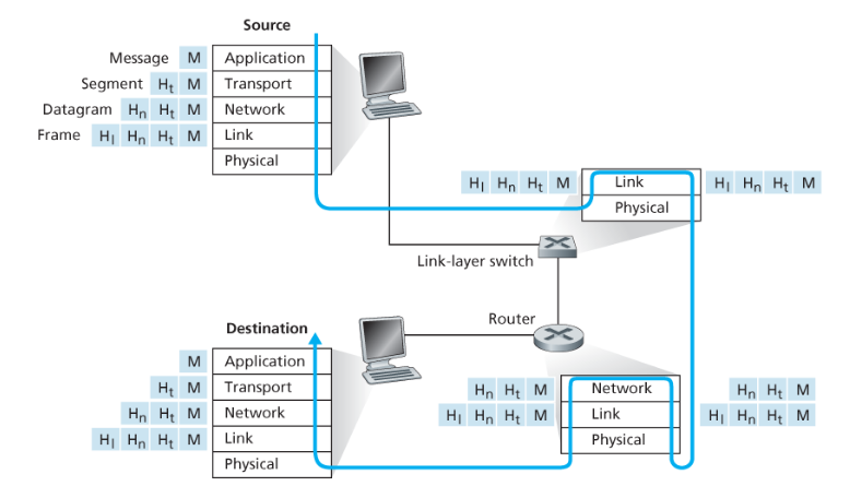
As you can see from the figure, link layer switches only implement the physical and link layer protocols (layers 1,2) , while routers implement up-to network layer protocols (layer 1 to 3) . Meanwhile, the end systems can implement protocols from all layers.
Networks Under Attack
Bot Net
The network of end systems affected by a particular (self-replicating) malware is called a “botnet”
Viruses
Viruses are malware that require some interaction to infect, such as email attachments consisting of malicious code, or a link that shouldn’t be pressed, or pop-ups that you encounter on sites I don’t want to name.
Worms
Worms are malware that can enter a device without any user interaction. A worm might enter because of some vulnerable network application running in the background.
DoS
Denial of Service (DoS) attacks render a network, host, or some infrastructure unusable by legitimate users. There are 3 categories of this:
Vulnerability attack
Send few well-crafted messages (application layer packets) to a vulnerable application or OS running on the target system. With the correct sequence of packets, the service can stop or the host can crash
Bandwidth flooding
Send so many packets that the target’s access link becomes clogged, preventing actual packets from reaching to the server.
Connection flooding
Create many half-open or fully open TCP connections to the target host. The host will become bogged down with these connections and it’ll stop accepting legitimate connections.
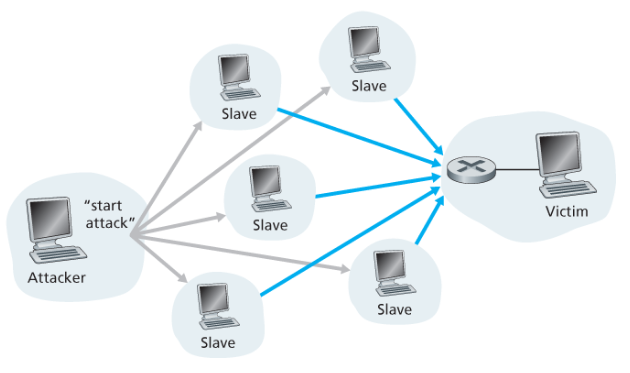
Distributed DoS (DDoS) attacks
Consider a bandwidth flooding attack. Usually, the upstream router will be able to figure out that the traffic from the attacker host is large and will block all traffic from the source, preventing the attack.
To avoid this, the attacker can send the packets in a distributed manner.
To send packets to destination at rate , the attacker will have multiple (say ) “slaves” send packets, each at rate to .
Packet Sniffing
Since radio spectrum is a shared medium, you can extract all the packets sent or received by the devices close to a WiFi access point, store it all offline, and then process it using some heavy computation later to extract sensitive information about the people who used that WiFi access point.
To extract the packets, one uses a passive packet sniffer. That is, the packet sniffer only detects the packets, but doesn’t send any packets. This makes it impossible to detect the packet sniffer.
The best defence against a packet sniffer is cryptography.
IP spoofing
It’s rather easy to create packets with arbitrary source address, content, and destination and to transmit this hand-crafted packet into the internet.
This means that an attacker can impersonate and deceive with efficiency.
Not need for manual spear phishing and pretending to be a person, when you can just impersonate directly.
This can be solved using “end-point authentication”
Chapter 2
Principles of Network Applications
Application Architecture
While network architecture describes how a bunch of computers are connected, an application architecture describes what roles the computers perform for an application distributed over the computers in a network
2 types of app. arch.
Client-server
Here, there are a bunch of servers that the clients communicate with. Thus, the clients communicate with each other indirectly, through the server.
The servers have a fixed IP address.
P2P
In person-to-person architecture, there is no reliance on a server.
The computers (peers) interact with each other directly.
Hybrid architecture
Some application do part of the process in a P2P manner and other parts using servers.
For example, a typical messaging application establishes connection with fixed servers to get the IP addresses of the users. So, when a user want to connect to another user, it can fetch the IP address of that user from the server, and then request a P2P connection.
P2P architecture is self-scalable, since there’s very minimal server usage.
Of course, this decentralisation comes with increases security threats.
Process based communication
The communication in application layer happens when a process running of end system sends messages over the network to be read by process running on end system .
Of course, this repeats like a table tennis match, with many round trips.
The process that started all this by requesting a connection is called the “client” process, and the other one is called the “server” process. This terminology is independent of app. arch. . Even in P2P , there are client and server processes.
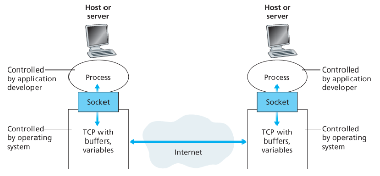
Socket
The communication between processes happens through a software interface called a “socket” .
The socket is the “application programming interface” (API) for the application developers.
Port
Since the communication is actually between , and not just , so the sending process must also specify the “port” on which is running on .
You must have seen port numbers being used. Say, for docker containers, or for connecting to a database, or some LLM API, or while using a file transfer application, or SSH, or anything related to the internet.
There are some unsaid rules for deciding the port. Conventionally,
- A web server is ran on port 80
- A mail server (using SMTP) on port 25
- A development server runs on port 8000
Transport layer services available
Since there can be many transport layer protocols to choose from for a socket, we need to consider the services that can be provided by different protocols
Reliable Data Transfer
The application layer won’t have to worry about packet loss or failed message transfer.
This may not be needed in loss-tolerant applications, like voice call, where packet loss is fine.
Throughput
There are 2 kinds of applications :
- Bandwidth-sensetive : throughput must not be below a threshold value throughout the session. Eaxmple : voice call
- Elastic : Throughput can vary, and can even drop to 0 at some points, and the application will still be fine. Example : File transfer
Here, by “throughput” we mean the instantaneous throughput.
Timing
Guarantees for the end-to-end delay for the packets.
This is useful for things like Multi-player games, where the time between a key-press and the action being done by a character on the screen should be minimal.
Security
- Confidentiality (encryption)
- Data Integrity
- End-point authentication
SSL
Neither TCP or UDP provide encryption. To deal with this, the internet community has developed an enhancement for TCP called Secure Sockets Layer (SSL) . This provides all the Security services (encryption, data integrity, end-point auth.) for a transport protocol.
Note that enhancements on TCP to give SSL are done in application layer, not the transport layer. In then end, everything still relies on TCP.
Basically, an SSL socket will take the cleartext (un-encrypted) data, encrypt it, and then pass it to a TCP socket.
Structure of a Web page
- An object is any file on the server, such as an HTML file, a PNG, or whatever
- A web page is a base HTML file plus the objects referenced by this file.
- The base HTML object references the other objects using URLs .
- Each URL has two parts :
- hostname of the server
- object’s path name
For example, in
http://www.someSchool.edu/someDepartment/picture.gif, theww.someSchool.eduis the hostname and/someDepartment/picture.gifis the path for the GIF file.
Non-persistent and Persistent Connections
For an application layer protocol, the usual procedure is :
- client process requests a connection
- server process sends a message back to say “OK”
- The actual protocol starts and objects are transferred.
Now, the way that objects are transferred from server to client describes if the connection is persistent.
In case all the files are transfered using the same connection, it’s said to be persistent.
If for each file, a new connection is made, it’s non-persistent.
Time needed for fetching
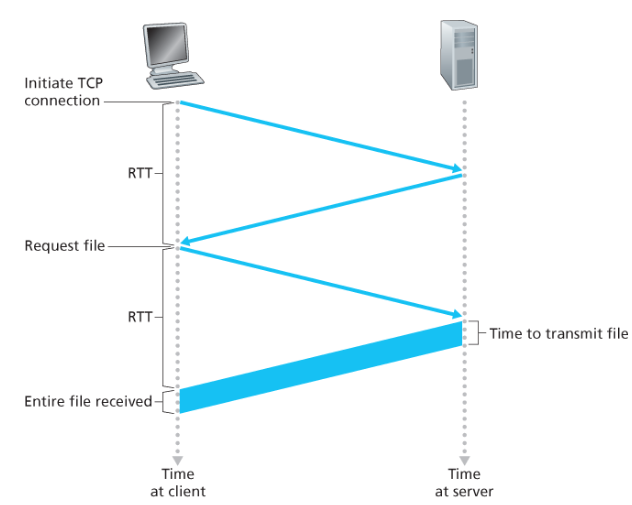
Here, RTT is short for “Round Trip Time”
Since there are three lightweight message streams sent before the transfer, this is called a “three-way handshake” . Each of these message streams need time.
This is for a non-persistent connection. This used to happen in HTTP 1.0
With a persistent connection, the first RTT happens only once, not for each object. This is what would usually happens for a GET using HTTP 1.1 .
Pipelining
While requesting multiple objects in a single connection is better than the non-persistent alternative, there’s an even faster method.
Instead of waiting for the transfer of the first file from the server to the client to complete, before the client can ask for another file, the client could not wait and just ask many times.
This is pipelining. By the time the first file is transferred, the second request has already arrived, and so the second file’s transmission starts right away.
HTTP
The great “Hyper Text Transfer Protocol” …
There are 2 types of HTTP messages :
Request messages
Theses are the messages sent by the client process
For example,
GET /somedir/page.html HTTP/1.1
Host: www.someschool.edu
Connection: close
User-agent: Mozilla/5.0
Accept-language: fr
Response messages
Messages sent by server process
For example :
HTTP/1.1 200 OK
Connection: close
Date: Tue, 18 Aug 2015 15:44:04 GMT
Server: Apache/2.2.3 (CentOS)
Last-Modified: Tue, 18 Aug 2015 15:11:03 GMT
Content-Length: 6821
Content-Type: text/html

(data data data data data ...)
HTTP request messages
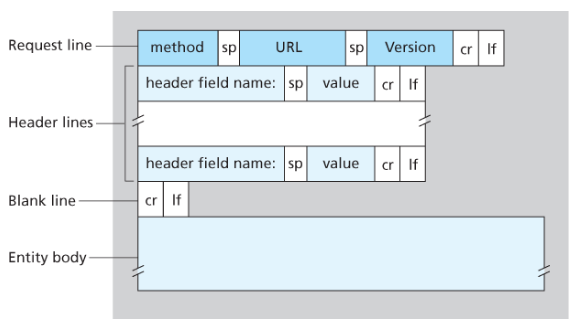
Here,
spjust means “space” ,crmeans “carriage return” (\r) andlfis “line feed” (\n)method
- GET : fetches an object based on requested URL
- POST : still fetches an object, but also uses the values of input fields in a “form” element to tell the server what to return.
- HEAD : Similar to GET , but the object body is left out in the response. This is used for development purposes
- PUT : Used to upload objects to Web servers.
- DELETE : Used to delete an object on a Web server
- PATCH : Fixes an object
URL
This is the path of the object on the server.
For example,
/somedir/page.html
version
This is the HTTP version that you want to use.
For example,
HTTP/1.1.
Header fields
One popular field is
Host, in particular, the destination host. For example,Host: www.someschool.eduYou may think this is unnecessary when there’s already a TCP connection, but it’s used by Web proxy caches.Another popular header field is
Connection. This specifies whether to close the connection, or keep it open. For example,Connection: closeTwo other headers are
User-agentthat is the browser type that is making the request (e.g.Mozilla/5.0), andAccept-languagethat specifies the language (e.g.frfor French) to return the web-page in (if that translation is available) .The last one is a “content-negotiation” header.
Entity body
This is empty for a GET request, while filled for a POST request. Basically, the values entered in the form fields from where the POST request originated.
Note that a form is not just limited to POST. It can also use GET, in which case the values are attached to the URL itself, delimited by some special character, such as
?.
HTTP response messages
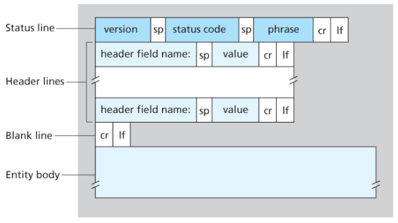
version
The same are version field in a request message. For example,
HTTP/1.1
status code and phrase
Indicates the result of the request. Some examples are :
200 Ok: everything went correctly and information is sent back.
301 Moved Permanently: Requested object has been moved on the server to a new location. The new URL will be provided in theLocation:header of the response
400 Bad Request: Generic error when the request couldn’t be understood by the server.
Cookies
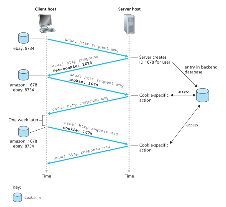
If you want the server to remember a client, it can assign each client an ID and send back a “set cookie” header, such as :
Set-cookie: 1678When this cookie is recieved by the client’s browser, it adds it to a cookie file as a
hostname: cookiepair. Then, for future requests by the client, the cookie is added in the request asCookie: 1678.Although cookies make the whole experience easier for the user, it can also be considered as a breach of privacy, since the database can store information about the user.
Web Cache / Proxy server
Similar to the cache in a computer, a proxy server keeps copies of recently requested objects from a actual server.
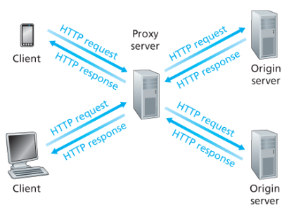
Companies and institutes use this a lot since the companies’s devices will not want to connect to all of the internet, but mostly the institute related servers
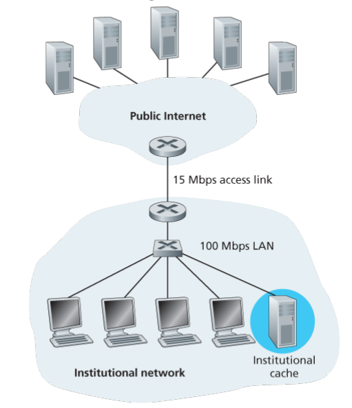
Ok, but how does a cache actually help. Consider this network :
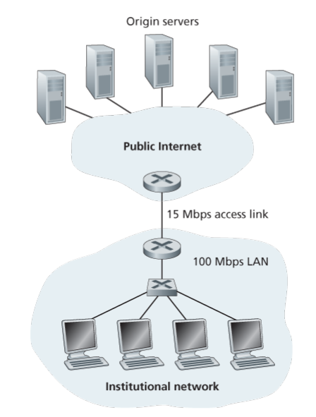
The 15 Mbps access link is part of the access network for the institution as a massive “end” system.
Suppose the devices of the institute, all combined request stuff from particular set of servers at a rate of 15 requests per second, with each request being about 1Mbit in size.
Then, the rate at which data need to be tranferred on the access link is 15Mbps , which is the maximum capacity that the access link can provide. Thus the traffic intensity is 15Mbps / 15 Mbps = 1 , barely at the edge. This will of course cause queue delays, on average, in minutes. Meanwhile delay for the LAN links will be just, say 0.01s
To avoid this, rather than upgrading the access link’s speed (a costly thing), the institution can set up a web-proxy.
The hit rate for the proxy will be (usually) 0.2 to 0.7 . Let’s take the scenario of 0.4. This means that the traffic intensity on the access link comes down to 0.6 which, considering the exponential relationship of traffic intensity and queue delay, is pretty good. It reduces the time from minutes to just milliseconds.
Then, the only relevant delays are the internet delay and the delay due to the LAN, say 0.01s.
Let’s also assume that the requests that are missed suffer a combined delay of 0.01s due to the LAN and the access link.
Thus, the average response time for the end user is :
internet delay
Just to recap, it is the delay in the packets transferred to the first router in the access network (usually in the ISP office) .
Conditional GET
This is related to how to know that you have to update a web cache.
Unlike in computer architecture, the contents of an object on a server can change since multiple users are interacting with it asynchronously. So when a user requests an object, already stored in the cache, we don’t actually know if the object data is correct (recent) or not.
To solve this, the web cache must update its data regularly. This is done using conditional GET.
For example, suppose a user want to get some object, it send a GET message like this to the cache :
GET /fruits/kiwi.gif HTTP/1.1
Host: www.exoticqecusine.com
Then, this message is forwarded to the server from the cache.
The server responds,
HTTP/1.1 200 OK
Date: Sat, 3 Oct 2015 15:39:29
Server: Apache/1.3.0 (Unix)
Last-Modified: Wed, 9 Sep 09:23:24
Content-Type: image/gif

....data....
The cache of course forwards the message, and caches the object, but now it also knows the
Last-Modifiedfield. This is used for the conditional GET.Now, when another user, a week later wants to get the same object, rather than just sending the cached object, the web-cache first verifies if the object is latest. To do this, it sends a conditional GET message to the sever :
GET /fruit/kiwi.gif HTTP/1.1
Host: www.exotiquecuisine.com
If-modified-since: Wed, 9 Sep 2015 09:23:24
If the object on the server was not modified, then the server sends this response :
HTTP/1.1 304 Not Modified
Date: Sat, 10 Oct 2015 15:39:29
Server: Apache/1.3.0 (Unix)
There is no entity body attached and thus, there is no extra load on the link due to this message.
Electronic Mail
The 3 components involved
- User agents
- Mail servers
- Simple Mail Transfer Protocol (SMTP)
Mail server structure
There are 2 main things :
mail queue
This is a queue of mails to be delivered to other mail servers and eventually to the user agents connected to that server.
If the other mail server is down for a mail, then it’s just put back into the queue. Re-attempts are done usually at intervals of 30s
If a mail stays for too long (usually many days) in the mail queue, it is rejected and the user that wrote the mail is notified through yet another mail, generated from the mail server ofc.
User mailbox
This is a list of mails for a particular user, namely their inbox . The moment that the user opens gmail or outlook, the mails in the user mailbox are sent to the user agent (user device).
Direct Server-to-Server connections
There are no “intermediate” or “central” mail servers. There is no hierarchy at all. The mails in a mail server will only be sent to the destination directly using TCP. They won’t be forwarded to a bigger mail server.
Restriction on data format
Unlike HTTP which can handle any arbitrary binary data, SMTP can only handle 7-bit ASCII characters.
So, everything has to be converted to ASCII strings before sending, including images, audio, etc.
Then the strings must be encoded back.
- Just like HTTP, SMTP has a client (sender) side and a server (receiver) side.
Actual protocol :
This is done in 3 parts
- SMTP Handshake
- Mails
- Closing
These stages aren’t formal. I just came up with it.
SMTP Handshake
Suppose there are mail servers A (crepes.fr) and B (hamburger.edu) and A wants to send mails to B.
First, a TCP connection is established. Then we proceed with the handshake.
B first introduces itself and tells its status .
220 hamburger.eduTo this, A introduces itself as
HELO crepes.frThen B greets A as
250 Hello crepes.fr, pleased to meet youI’m not making this shit up. This is the actual protocol.
This marks the end of the handshake.
sending Mails
After the handshake, A tells B that there is a mail from a user
MAIL FROM: <alice@crepes.fr>Then B checks if the sender is ok as
250 alice@crepes.fr ... Sender okThen, A specifies who the mail is for (the recipient )
RCPT TO: <bob@hamburger.edu>Again, B checks if the receiver is ok.
250 bob@hamburger.edu ... Recipient okNote that there might be multiple receivers, all connected to the same server B. In such a case, the last 2 steps can repeat.
Finally, A asserts that it’s going to send the contents of the mail as
DATATo which B replies as
354 Enter mail, end with "." on a line by itselfWhat this message means is that A can start sending data, and to end the data section, it has to send just a “.’” alone on a line.
A then sends the data as
Do you like ketchup?
How about pickles?
.
The last line has the “.” needed to end the data section.
To this B replies
250 Message accepted for deliveryThis whole process happens for all the mails that are to be sent from A to B. These can have different sender, receivers, etc.
Closing SMTP connection
Once all the mails are sent, A sends
QUITAnd finally, B replies
221 hamburger.edu closing connection
Mail message formats (headers)
Perpheral information for a mail is the metadata about the mail, such as the “from”,”to” and “subject” fields.
Some of this metadata is explicitely taken care of by SMTP, such as through the “MAIL FROM” and “RCPT TO” fields from the client side.
But it’s also a good idea to have the full metadata using headers. For example :
From: alice@crepes.fr
To: bob@hamburger.edu
Subject: Searching for meaning of life.
After these headers you need to leave a blank line and then start the body.
Of course all this is still inside the “DATA” section of the actual mail, as done by SMTP.
Mail access protocol
The reciever end system cannot just get the mail from his server the moment the mail pops in his mail box (inside the server) . Instead, the server “serves” the mail on-demand .
To do this, you can of course NOT use SMTP, since it’s a push protocol.
So, you need a different protocol. Popular ones are
- POP3
- IMAP
- HTTP
POP3
The Post-Office-Protocol (3) works like this :
authorisation
- The receiver user agent (call it B) establishes a TCP connection with the mail server (call it M) on port 110
- M send a
+OK POP3 server readyto indicate it’s available.
- B sends the username as
user bob(“bob” is the user name)
- M responds
+OK
- B sends the password as
pass hungry(here, “hungry” is the password)
- M responds
+OK user successfully logged on
Note that the responses from M will either start with
+OKindicating .. an OK execution, or with a-ERRindicating that the execution of last message by the user B didn’t happen correctly.For example, if you make a spelling mistake in a keyword M will give an error.
transaction
This is when the actual transfer of mails happens.
- B starts with
list.
- M reponds with a list of indices for the mails and their sizes in KB . At the end, there will be a single dot .
1 498
2 912
.
- Then, B will try to retrieve mails from M. To do this, it issues the
retrcommand asretr 1
- Then, M will send the data for the mail indexed 1 (as in the output of
list) . This will be followed by a singe dot on a line to mark the end.
- Another thing that B can do is mark mails for deletion from M once the conversation is done. For example, if B issues
dele 1, then M will remember that it has to delete the mail that was indexed 1 once this session is closed.
- There will usually be a chain of
retranddelecommands.
- Once all that is done, B issues
quit
- To that M responds
+OK POP3 server signing off
- B starts with
There are some issues with this method.
One big issue is of multiple devices for the same user. If the user who uses agent B also uses agent C, and B downloads the mails from M and deletes them, then C will never get the mails. So, the inbox will depend on the device.
The paradigm where B downloads and deletes is called the (guess what) .. the download-and-delete method.
Another paradigm is download-and-keep where B will download the mails, but not delete it. This of course means that the mail server needs to store the mails permanently … not nice.
IMAP
This is a more complex and more flexible protocol that POP3. One big feature it has is that of folders .
Every mail is kept is some “folder” in the mail server. When a mail first arrives, it enters the receiver’s INBOX (the same as mail box) folder on the server.
- The recipient can move the mails to different folders and create new folders.
- Of course, the recipient can also read and delete the mails.
- Moreover, the recipients can also search for mails in a particular folders based of different criterion. Of course, simple listing is also possible as a tiny subset of all the things this feature enables
- The recipient can also obtain only parts of the mail rather than the full mail, unlike in POP3. This allows for things like GMail to be built easily.
HTTP for mail access
This is what we call “web based e-mail” . Do note that only the mail access (and maybe the transmission of mail from A to its mail server) is through HTTP. The mail servers still interact using SMPT.
You already know how HTTP operates.
Now all you have to do is just first get an object from the mail server M that describes the existing mail, download the mails, delete the mails (and update the object enumerating the mails), etc. But this also means you can do weird stuff such as create new mails.. for yourself .. idk what that even does internally. Or update a mail .. some serious legal issues here . Thankfully the mail servers are protected against such things and you can only do operations that applications such as gmail allow you to do, even if you use HTTP directly.
DNS
What does it do ?
Although each host can technically be identified by its hostname, that isn’t how routers do it. They rely on IP addresses.
The Domain Name System converts the hostname to an IP address.
which layer ?
This is actually an application level protocol, just like HTTP.
Unlike HTTP and SMTP, this thing (DNS) usually runs on UDP and not TCP. But you can also make it run on TCP if you want.
Network architecture
You have many DNS servers running at key places.
The servers are usually UNIX servers and run the Berkely Internet Name Domain (BIND) software.
Your ISP usually has the IP address of the closest DNS servers stored somewhere in your access network infrastructure. Even your device might have this information.
Usage overview
DNS uses port 53
When a client wants to get the IP address(es) associated with a hostname, it sends an enquiry to the nearest DNS server
The query is eventually answered and then the client proceeds with creating a TCP connection (or doing whatever it wanted to do) from the IP address obtained.
Nature of mapping
The mapping from hosts to IP addresses in neither injective, nor a function.
You can have one host (and thus one IP address) with multiple hostnames, and multiple devices (say, servers) with different IP addresses but the same hostname.
Host aliasing
If a hostname for a server (or bunch of servers) is rather complicated, it might be beneficial to replace it with a simpler host name.
This is done by host aliasing. The original hostname is called the canonical hostname and the new hostname is an alias for the original. Basically, it points to the canonical hostname, and the canonical hostname points to the IP address.
This thing is rather important for something like a mail server.
When you want to connect to any mail server for a mail application, you of course won’t know its actual hostname. Instead, what you’ll know is the alias name, which is the same for all mail servers (physical or virtual) that the mail application uses, for example
yahoo.com. You’ll use DNS to get back the canonical hostnames of all of these mail servers and then decide which one to connect to based on your location.
Load distribution
If a content provider has multiple servers and it wants to distribute the load evenly across them, then what it can do is :
- have a common alias for all the servers
- on the DNS server side, return the list of IP addresses with that aliased hostname, and rotate it after that (in the database ofc)
- On the client side, use the topmost IP address in the rotated list
How does DNS work ?
The domain name is made up of parts separated by
.. For example, fors='a.b.c'the parts aretokens = ['a','b','c']. The DNS structure is basically a very big tree with each node having a string made up fromtokens[-l:]for somel. The 0th level contains only the empty string.Now, the servers in the 0th, 1st and 2nd layers are given names “root servers”, “top level domain servers” , “second level domain servers” .
Each server is associated with a unique string, namely
'.'.join(tokens[-l:]) . This string is called a “zone” . For example, there a root server is associated with zone , TLD servers can be associated with zonescom,org,edu, etc., and a SLD server can be associated withfacebook.com,umass.edu, etc.Each server stores the IP addresses of many domains that are “in the zone” . All these domains have the zone string as a suffix.
But there are also domains with zone as suffix, for which it doesn’t store the IP address and instead stores the hostname of another DNS server that manages a zone with larger string (for example,
facebook.comis a larger string thancom) . For example, on a server managing zonecom, the IP address ofwww.facebook.commight not be stored. The DNS server will then return the hostname of another DNS server, one that manages the zonefacebook.com. All this is very similar to inodes in OS.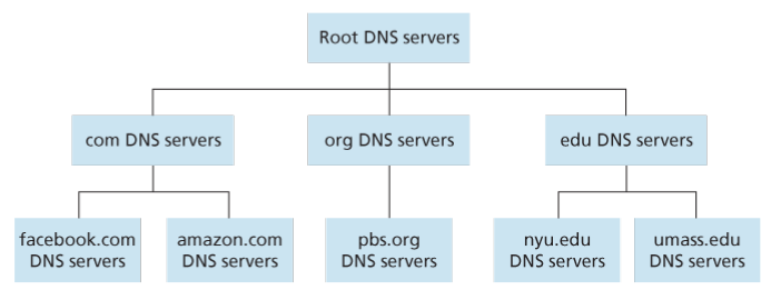
Moreover, the local server stores addresses of root servers.
So, to get the IP address of a hostname, say
www.facebook.com, a local DNS server will first ask a root server for the IP addresses of TLD servers associated withcom. It will pick one of these TLD servers, and it will then ask that TLD server for the IP address of servers associated withfacebook.com. Once again, it will pick one of these servers and will directly ask it for the IP address ofwww.facebook.comwhich will be stored in the DNS server.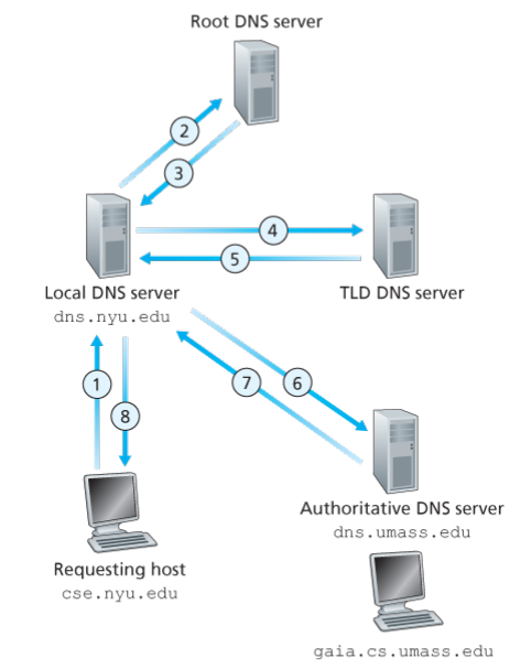
Authoritative servers
Servers that are tasked with managing queries in a particular zone are said to be authoritative of that zone. For a particular query, a server is authoritative of that query if it directly answers it rather than delegating it or through recursion.
This is assuming there is no cache stuff going on.
delegation
This is when, instead of answering a query by itself, a server gives the address of another server which works with queries more similar to yours. For example, a server authoritative of zone
comdelegating the querywww.facebook.comtofacebook.com.The new server is called the delegated server.
recursive query
This is when a server delegates a task completely to another server, basically making that server actually do the job , then takes the answer and returns it to the device that the query came from, without that device ever having to communicate with the delegated server.
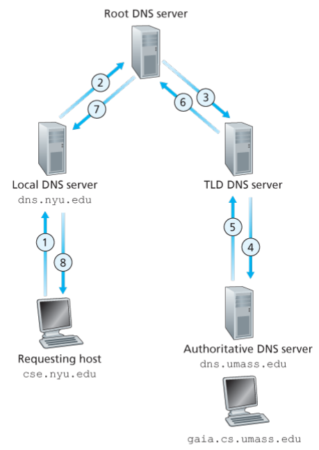
iterative query.
Here, the server returns the hostname or IP address of the delegated server. For example, here the local DNS server is querying iteratively.
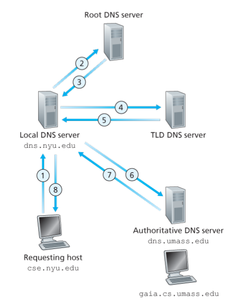
DNS caching
There are only 400 root DNS servers in the world. You can imagine the kind of inefficiency this would lead to if every DNS query passed through the root servers.
Thankfully, the DNS servers can cache the answer to the queries that they are supposed to answer (and not delegate) so that the next time a person asks the same query, there’s no need for the DNS server to ask other DNS servers. Note that a server with zone
comis not directly authoritative of the querywww.facebook.com, but it can still cache it and then answer it.In fact, a very small portion of the total number of DNS queries ever reach the root servers.
DNS records and messages
A resource record is a 4-tuple with named fields “Name”,”Value”,”Type”,”TTL” .
- “Type” field can be one of
A,AAAA,NS,MXandCNAME.
- For type
Arecords, the name field contains a hostname and the value field contains the IPv4 address.
- For type
AAAA, it’s the same as typeAexcept you have IPv6 address.
- For type
NS, the name is a domain and the value is the hostname of a delegated DNS for that domain as the zone.
- For type
CNAMEthe name is an alias hostname and the value is a canonical hostname.
- For type
MX, it’s the same as typeCNAMEexcept that it’s the canonical hostname of a mail server, not just any server. Since usually, a companies mail servers and normal servers have the same alias, the records need different types to distinguish them,
- “Type” field can be one of
- For the university network, the hostname (say
iitgn.ac.in) is mapped to the IP address dynamically using DMCP . This is done automatically when you connect to WiFi or Ethernet . Moreover, even the IP address for your device is decided by this.
BitTorrent
- There is a infrastructure node called “tracker”
- The torrent is basically a bunch of hosts all trying to distribute a file.
- For hosts in the torrent, the distribution time in a centralised architecture would be
- In a P2P architecture, like bit-Torent , the distribution time is roughly .
- Each device first contacts the tracker to get a list of IP addresses for all the devices in the torrent.
- Then, it requests parts of the file from a fixed number of peers. Some devices will actually transmit.
- Now, it also measures the download rate from each device. The top 4 peers (ones with highest rates) are called unchocked peers.
- When the device wants to contribute back (upload) , it also picks another peer randomly that is “optimistically unchocked”
- The unchocked and optimistically unchocked peers are ones that get data from the said device, while other peers don’t.
- To decide what part of the file to upload, the device will use a rarest first policy, i.e. the part that is present in the least number of peers is uploaded in the torrent.
Dash
Dynamic Adaptive Streaming over HTTP (DASH) is a method in which videos are partitioned into parts, for all versions (different bitrate for each version).
The reciever get the appropriate version of a part based on the download speed, the excess (not being played right now) number of parts already recieved, etc.
The different versions are specified by URLs .
All the information is written into a manifest file.
CDN
- Content distribution networks are usually used for video data.
- Some CDNs are private. For example, the CDN for YouTube is owned and maintained by Google.
- Some CDNs are third-party. That is, they distribute content owned by other companies through their network. For example, Akami, Limelight and Level-3 operate using 3rd part CDNs
- CDNs can either “Enter deep” , that is, have their servers are on the access ISP networks directly.
- Or CDNs can “Bring Home” the ISPs by having their servers on IXPs
- For third party CDNs, they must intercept the requests with hostname of customer company and then send the video on the company’s behalf. This happens by using one of the customer company hostnames (usually a domain associated with the actual videos and not just the company’s general web services, like a website) as an alias for the third party DNS server’s hostname.
- Do note that once the DNS flow has been handed to the CDN provider, the provider’s DNS servers must also figure out which CDN server should the user must be connected to. This is done by a “Cluster Selection Strategy”. The CDN provider’s DNS server will already know the IP address of the person requesting the video. This can then be used to find the location and locate a geographically close server and send its IP address back.
Chapter 3
logical connection
This is the view of the connection from the application’s perspective.
Although A and B may be connected by a complicated path, from the application POV, it’s as if they are connected by a single link.
- transport layer is not there in routers
- transport layer protocols provide logical communication between processes, while network layer protocols do it between hosts .
UDP in brief
- User Datagram Protocol
- unreliable (packet loss can happen)
- connectionless
- Does process-to-process data delivery (multiplexing and demultiplexing)
- error checking (checksum)
- Sometimes UDP segments are refered to as “datagrams”. That is an archaic terminology and should not be used
TCP in brief
- Transport Control Protocol
- reliable
- connection oriented
- congestion control
demultiplexing
Delivering the data segments to the correct port based on some fields in the segment
multiplexing
Encapsulating the data chunks along with header information from various ports.
Port numbers
- 16 bit (unsigned) numbers
- Numbers ranging from 0 to 1023 are “well known port numbers”
- In Python socket programming, a socket is by default assigned an unused port number that isn’t well known.
- In Python socket programming, you can bind a socket to a particular port number.
Connectionless multiplexing and demultiplexing
- Each segment has a destination port number and source port number
- There can be multiple devices sending segments to the same port on a device. The devices are distiguished by their IP address by the application , not inherently by the connection.
- The source port number serves as a return address. It informs the receiving process which port to send packets back to (for acknowledgements and other things).
creating a TCP connection
- The server has a “welcoming socket” running at some port, say 12000
- The client first sends a connection-establishment request, which is just a TCP segment but with the connection-establishment bit set to 1.
- The connection-establishment request is identified by the OS and sent to the process running on 12000 for further processing.
- The process running on 12000 then creates a new TCP connection (and thus, a new TCP socket).
A TCP socket is identified by
- source IP
- source port
- destination IP
- destination port
Any segment that matches is demultiplexed to the socket.
In comparison, UDP sockets are characterised only by the source and destination port numbers.
- One process can be running multiple threads, each managing a separate socet. So, there is no one-to-one correspondence of processes and ports. It’s only instructive.
- Web servers use the same port (80) for the welcoming socket and the actual TCP sockets.
UDP checksum
The checksum is just the 1’s complement of the sum of the 16 bit words in a segment, not caring about overflows.
Now, at the recieving end, if all 16-bit words are added (including the checksum), the value should be 1111111111111111 (binary).
Why checksum
Although some link layer protocols already provide error checking, it’s not ensured that this will happen for every link.
So, you need an end-to-end level error check.
This is an example of the “end-to-end principle”.
UDP length field
This the number of bytes in the actual UDP segment, not just the application data message. Since UDP header are 4 feilds, each of 2 bytes, the length is 8 more than number of bytes in application message.
Simple ACK,NAK based RDT
Sender
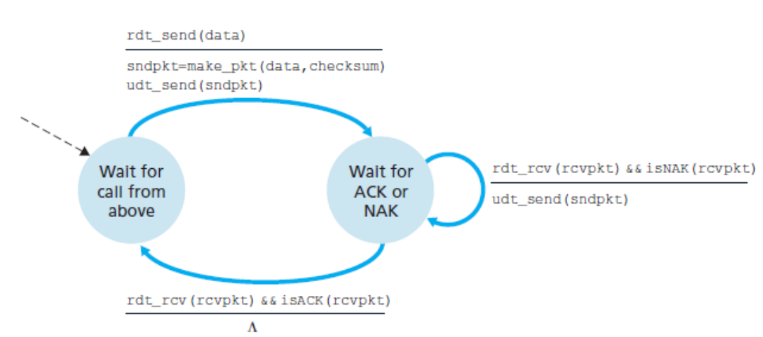
Receiver
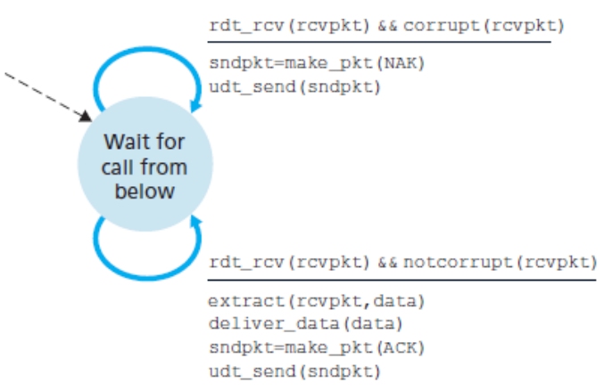
Since the sender cannot react to the
red_sendevent when it is in the waiting state, it is thus a “stop-and-wait” proptocol.Flaws :
- ACK,NAK packets can be corrupted
- Packet loss is not protected against.
ACK,NAK and 1 bit sequence number
Sender
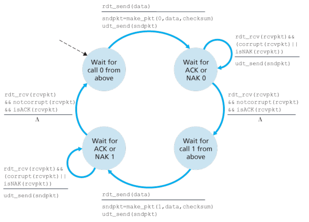
In case of corrupted feedback or NAK, the sender simply sends the packet again. Otherwise it moves to the next packet.
The feedback does not have the sequence number. But since this is stop and wait, the acknowledgement can only be for the current packet.
Receiver
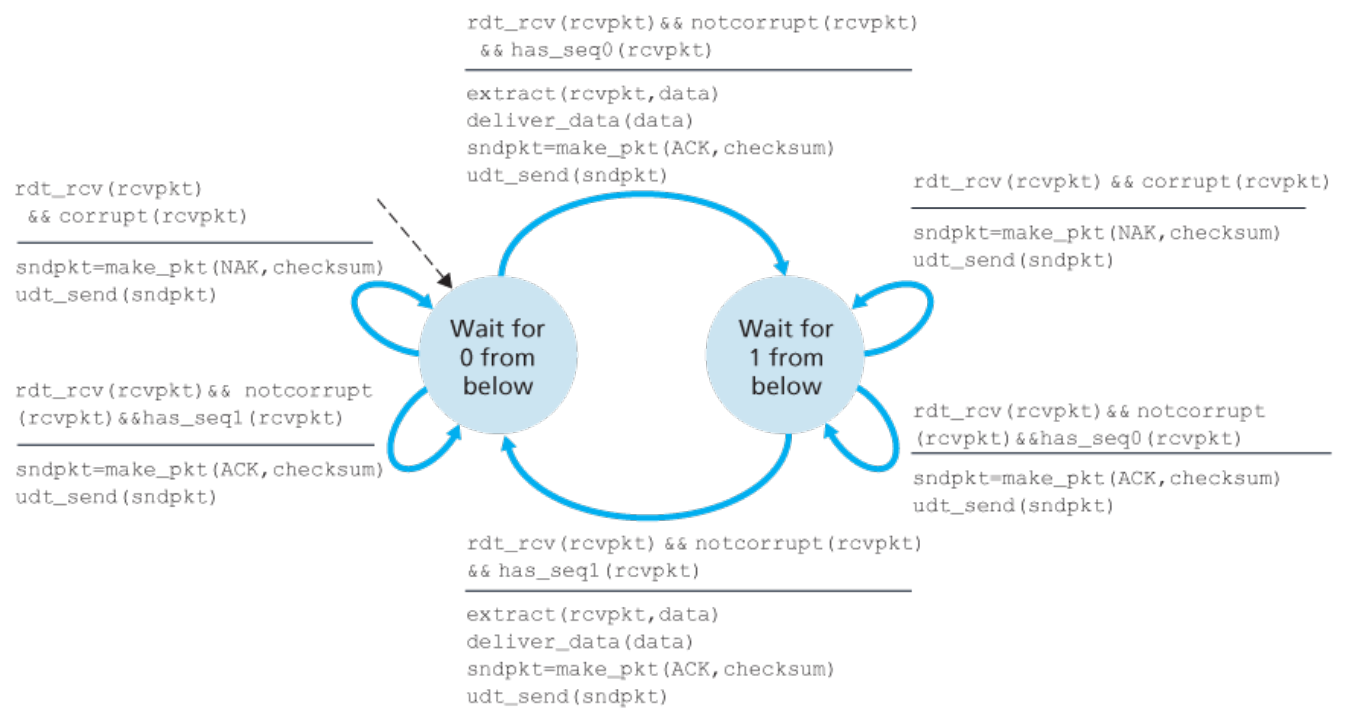
In case the sender got a corrupted acknowledgement, it will just send the packet again. But the reciever is assuming it’ll send a new packet.
So, in case the sequence number is not the expected sequence number, just send the acknowledgement for the sequence number again and don’t do anything else.
Only ACK and 1 bit sequence number
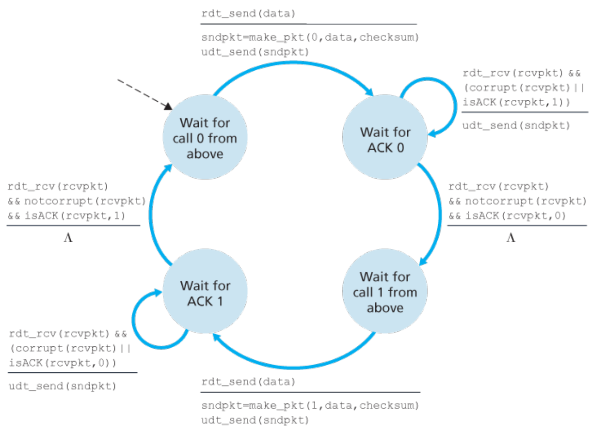
sender
receiver
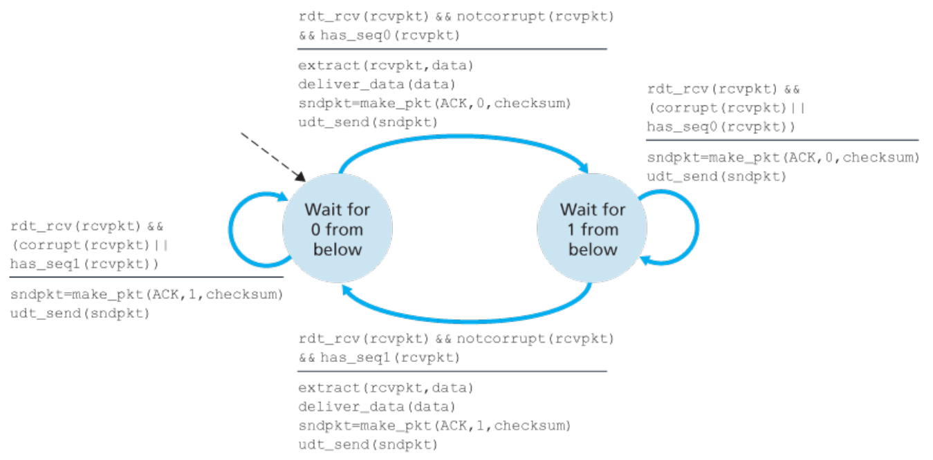
Here, is acting as when sequence number of currently sent packet is 0, and vice versa.
Dealing with packet loss
The way to identify packet loss is to have a timeout event on the sender side, with the timer set when you reach a waiting state, or reset when the event fires.
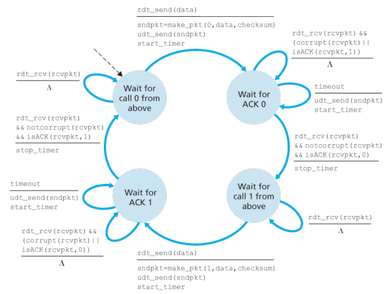
For the receiver, whether the sender sent the packet again due to corruption or due to timeout is irrelevant.
The protocol built till now is called the “alternating-bit protocol”.
Utilisation
This is the fraction of time that the sender is actually transmitting packets.
For a stop-and-wait protocol, it’s very low.
Go-Back-N
- The window size is the number of (unique) packets from the sender that can be on the wire at any given moment.
- The range of sequence numbers must be at least . Usually, it is much larger.
- Sender maintains an (virtual) array such that is the packet with sequence number .
- The sender maintains base which is the sequence number of the oldest unacknowledged packet.
- The sender also maintains the “next sequence number” that is the the sequence number it will assign to a packet next time it is asked to send a packet.
sender : (where is a packet)
- if : reject and inform upper layer
- else :
-
-
- if : start timer
-
sender : timeout
- start timer
- for to :
-
sender :
- if : do nothing
- else:
-
- if : stop timer
- else : start timer
- The receiver maintains the variable “expected sequence number” which is the packet it will acknowledge next if it reaches.
- The receiver maintains the variable which is the last acknowledgement packet it sent. In case of corrupted packets, it just sends . This will either increment or not. If it doesn’t the sender will eventually have a timeout and will send the next packet.
receiver : :
- if :
- else :
-
- if :
-
-
-
-
- else:
Simple Repeat
- No cummulative acknowledgements. Only for single packets.
- Sender maintains array and where is the packet with sequence number and is whether an acknowledgement was received for it.
- Just like before, sender maintains with .
- Reciever maintains array where is whether or not packet with sequence number was recieved.
- Receiver maintains with .
- Receiver also acknowledges packets in range since there is a possibility of all of previous acknowledgements being corrupted or dropped, causing sender to send packets in that range again, while the reciever base has already shifted.
Multicasting
This is when the data sent from a host A reaches multiple hosts .
TCP, for example, is incapable of multicasting.
MMS
The Maximum Segment Size is the maximum amount of application data that can be put in a TCP segment
It is set by first finding the MTU and then setting it so that
MTU
The Maimum Transmission Unit is the maximum size of a link layer frame.
TCP buffers
The send buffer and receive buffer are spaces where the TCP segments are stored.
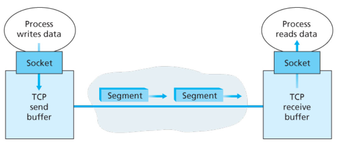
Each TCP socket has its own send and receive buffers (yes, 2 separate buffers)
TCP sequence numbers
The sequence numbers are for bytes rather than TCP segments. The sequence number feild in a TCP segment is the sequence number of the first byte.
TCP acknowledgement numbers
This is the next expected byte’s sequence number.
Note that TCP has a flag called “ACK”. It must be set to 1 for the segment to act as an acknowledgement (or carrying an acknowledgment). Otherwise, it’s simply data.
Initial sequence number (ISN)
The initial sequence number is chosen randomly (rather than setting it to 0). This is done so that the acknowledgements for any packets still on the wire from previous TCP connection with the same socket identifier (the 4-tuple) are not mistaken as acknowledgements from this session.
Retranmission Time-Out (RTO) estimation
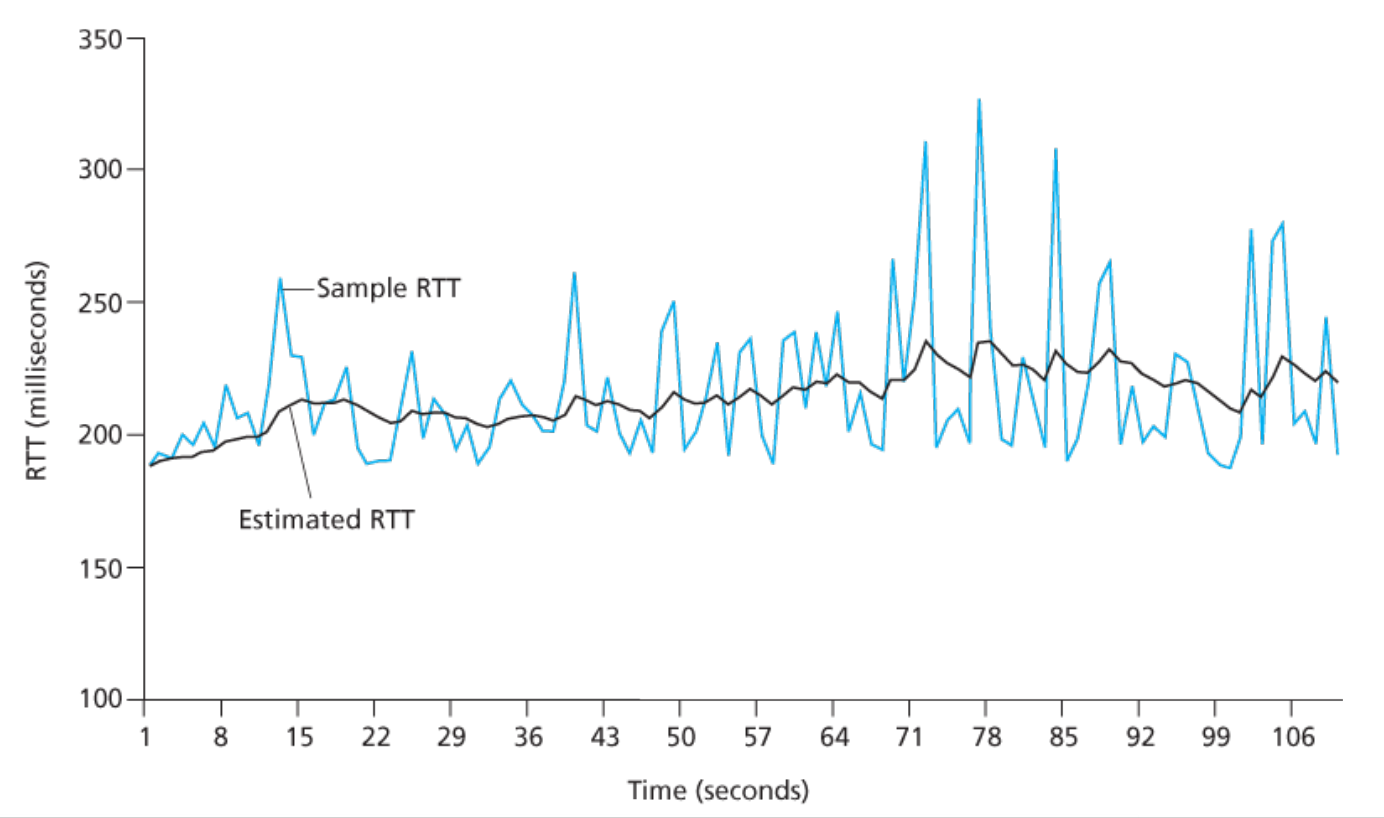
This is probably the most interesting part of this book. The timeout is estimated using exponentially weighted moving averages.
Iterative adaptation
For the segments that are sent once and are then acknowledged, the time from sending to recieving is the RTT for that particular segment. Call it for the such measurement. These measurements are done not for every segment, but are done so that at any given moment, exactly one segment’s RTT is being recorded.
From these measurements, you can calculate an EWMA as
Then, from that you can derive a measure of deviation of the estimate as :
All of this finally gives us the timeout interval as
The recommended values of are 0.125 and 0.25 .
Initialisation
Initially, you set the timeout interval to 1s (according the the RFCs). Then when you get the first measurement , you do and giving . From there, ther iterative process starts.
The EWMA smoothens out the actual measured values.
TCP RDT
- The receiver send cummulative acknowledgements. The acknowledgedment number is only valid when ACK is set to 1.
- The receiver can either discard out-of-order segments or buffer them.
- If the receiver decides to not buffer, it should send the ACK with its value when it encounters an out-of-oder segment.
- For delayed acknowledgement, the receiver waits for a bit of time before sending the ACK so that if another in-order segment arrives, it only has to send one cummulative ACK for both. When the other segment comes, it sends the ACK immediately for both.
- In case reciever is buffering the segments, it can either send selective Acknowledgements (SACK) or just send one acknowledgement when the reciever base is moved (the gaps are filled)
- The sender, on recieving data from upper layer just sends the packet and increments the next-sequence-number value. If the timer is not running (for example if before receiving data) then it starts it. The timeout interval is the moving average estimate.
- The sender, on timeout transmits the packet with smallest sequence number that isn’t ACKed only (unlike GBN which sends everything).
Also, every time timeout happens, the timer is restarted. In some modifications, the timeout interval is doubled.
- On receiving acknowledgement with acknowledgement number (strictly) greater that , the base is set to that number and if there are unacknowledged packets, the timer is started. The timeout interval is (re)set to the moving average estimate.
- In case SACKs are buffered on sender’s end, then you need to set to smallest unacknowledged byte’s seq. number on recieving ACK with number more that .
- For fast-re-transmit, if you recieve 3 duplicate ACKs (4 counting the original one) then you should also transmit the segment with the sequence number same as ack. number received. This would’ve happened regardless if you would’ve got only a stream of these duplicate ACKs and the timeout happened. Thus “fast” retransmit.
TCP flow control
- As the segments arrived in the receive buffer, they are processed at some rate. For the buffer to not overflow, the number of bytes that enter the buffer at any point must be lower that the “receiving window” which is simply the space left.
- You can compute receiving window size as seq. number of last byte received minus the seq. number of last byte processed.
- The amount of unacknowledged bytes on the sender’s end (which is basically ) must always be less that the receiving window.
- The value of receiving window is sent using the “window” field in the TCP header.
- In the case that the window value is 0 and the receiver doesn’t send anything after that, the sender could be perpetually blocked since the receiver only reacts. It doesn’t initiate converstation.. and if the sender is also not sending anything.. that relationship is dead.
To solve this, the sender needs to not take “no” as “no” and still send data, in particular 1 byte of data.
Creating a TCP connection (for real this time)
- The client chooses a random Initial Sequence Number (ISN) . The choice of this thing is critical to avoid security attacks and it a research topic.
The client sends an empty segment with this sequence number and the SYN field set to 1.
This segment is thus called the TCP SYN segment.
- The server (process), on receiving the SYN segment, also chooses an ISN. It then send a segment with sequence number set to this “server ISN” and the acknowledgement number set to . The ACK and SYN fields are set to 1.
This segment is called the SYNACK segment.
Note that in the old implementation of TCP, before sending the SYNACK segment, the server will allocate the butters and variables for this connection. This is a bad idea and leads to SYN flooding.
- Finally, on geting the SYNACK segment, the client also allocates buffers and variables to the connection.
It then sends a segment with SYN feild set to 0, no data, and the acknowledgement number as and sequence number as . This segment may also have a payload. At this point, we’ve entered the usual TCP flow.
- The next segment from the server will have sequence number .
- The client chooses a random Initial Sequence Number (ISN) . The choice of this thing is critical to avoid security attacks and it a research topic.
Closing a TCP connection
- The client sets the flag FIN to 1 in the last segment.
- The server acknowledges this segment and continues sending any remaining segments from its side.
- In the last segment the server sets FIN to 1.
- The client acknowledges.
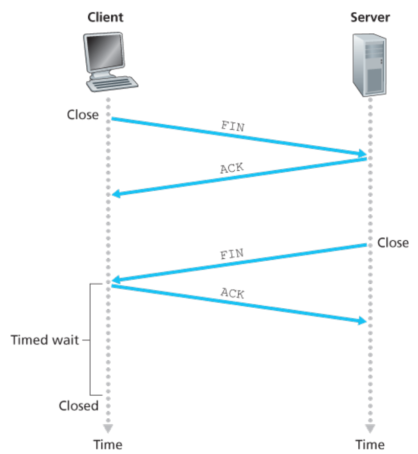
Note that the final ACK by the client will of course be a segment in itself. But it will not be acknowledged by the server. The server has already dissolved its socket and any segment with SYN set to 0 will be meaningless.
So, the client just sends the ACK, waits for some time and closes.
SYN flooding and cookies
Just like TCP connection flooding, there used to be an efficient DoS attack called SYN flooding.
The attacker sends a lot of SYN segments to the server. Since in step 2, the server is supposed to allocate resources for the socket before sending the SYNACK, thus the server gets overwhelmed, leading to DoS.
To prevent this, run a hash function with a secret seed, using the 4-tuple for the SYN segment (IP and port for source and destination).
Return the hash value in the SYNACK and require the next segment from the client to have this cookie as data.
Only once that happens should the server allocate resources for the socket.
(I wonder .. can’t the attacker just send the ACK without allocating resources then ?)
RST
A TCP RST segement is one with RST flag set to 1. This indicates that the port isn’t allocated to any process on the server side.
TCP cycle for client
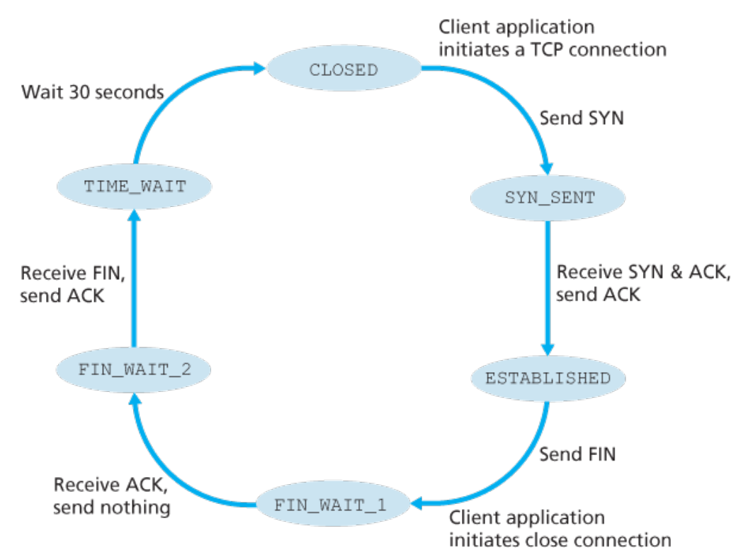
TCP cycle for server
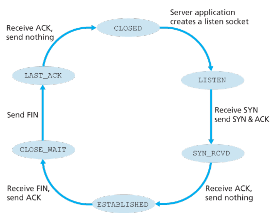
TCP congestion control
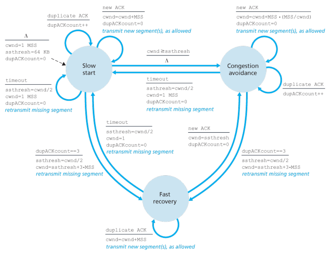
- For congestion window size and RTT of , the throughput can be approximated as . Thus, the utilisation is .
Slow start :
- For every new ACK received, . Thus effectively, in a RTT, the window doubles.
- On getting 3 duplicate ACKs in a row (condition for fast-retransmit), set and . Then, enter the Fast Recovery mode.
- On having a timeout event, do and
- If is achieved, then go to Congestion Avoidance mode
Congestion avoidance :
- For every new ACK, .
- For 3 duplicate ACKs, and . Also, enter the fast recovery mode.
- In case of a timeout, and . Enter the slow start mode.
Fast recovery
- For new ACK, and go to congestion avoidance mode
- For timeout, and and go to slow start.
- On getting the same duplicate ACK due to which you got to this mode, do .
Chapter 4
- An individual router does forwarding (a local operation), while the full network layer (as an infrastructure) does the routing of the packet (end to end).
- Forwarding happens using the forwarding table .
- The forwarding table maps the header values to interfaces (outgoing links) . This is based on PLA (programmable hardware, not a full blown processor.).
- The control plane routing algorithms decide the forwarding tables for each router,
- Usually the control plane is implemented in software, thus “Software-defined networking” or SDN for short.
- The network service model is the set of characteristics (rules) for end-to-end delivery of packets.
The ATM (yes, Any-Time-Money) network architecture implements
- in-order packet delivery
- bounded packet delay
- guaranteed minimal bandwidth
The Intserv network architecture provides
- end-to-end delay guarantee
- congestion free communication
- Despite internet’s network layer being only “best-effort” (really, no effort), it is adequate.
- When the switching/forwarding is based on link layer header, the packet switch is called a link-layer switch, and is NOT a router, and NOT a part of the network layer
The structure of a router
- Input port : This is where the incoming data arrives. Namely, it is one of the ends of a communication link. This is further made up of 3 parts, the physical layer stuff (ADC, for example), the link layer stuff (i don’t even know what happens here), and finally, the forwarding table. The packet’s header is used and the output port is decided here (remember, big combinational circuit, so no need to worry about the data).
Apart from normal data packets (which go to one of the output ports, there are control packets that go to the routing processor)
- Switching fabric : This simply connects the input ports to the output ports and passes information based on the output port values decided earlier.
- Routing processor : This performs control-plane functions, such as changing the forwarding tables.
- The forwarding table is copied from the routing processor to the input ports using a data-bus separate from the bus for the packets; for example a PCI (Peripheral Component Interconnect) . This allows for deciding the output port at the input port itself, rather than invoking the (central) routing processor.
- Input port : This is where the incoming data arrives. Namely, it is one of the ends of a communication link. This is further made up of 3 parts, the physical layer stuff (ADC, for example), the link layer stuff (i don’t even know what happens here), and finally, the forwarding table. The packet’s header is used and the output port is decided here (remember, big combinational circuit, so no need to worry about the data).
Input port processing
- The forwarding table uses “longest prefix match” to decide the port. Namely, it matches keys with the header to find the longest key which is a prefix of the header (binary ofc). This key’s value then is the output port.
- The processing happens in two stages, a “match” (finding the matching key) and an “action” (sending the packet to the switching fabric). This “match-plus-action” abstraction is more general and used by many network layer devices.
- There are content addressable memories called TCAM that are used for forwarding table lookup in constant time.
Switching
- Switching can be done via memory, a data bus, or a crossbar switch
Memory
When switching using memory, suppose the AMAT is , giving us a rate of packets per unit time, then since in a unit of time, both read and write operations have to be done, thus only packets are written out to the output ports. Thus, the bandwidth is bounded as .
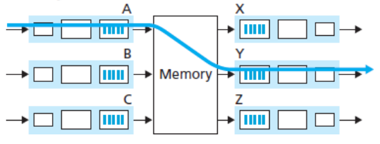
Bus
Switching over a databus is faster. The rate of transmission is just the rate of transmission for the bus.
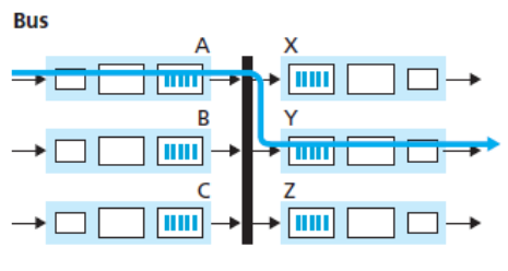
Crossbar (interconnect network)
A crossbar switch is intended to be non-blocking. If you have packets on input links A,B that want to go to output ports C,D then this transmission can happen simultaneously.
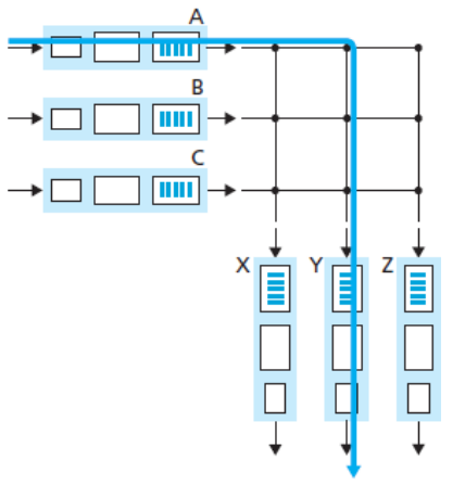
Queuing
- We have 3 different rates to worry about now.
- , the rate at which a single input port receives data.
- , the rate for the switching fabric
- , the rate at which a single output port sends the data.
- For input ports, if then there will be no queuing in the input ports.
- Head of Line (HOL) blocking is when a packet in an input port is blocked leading to blocking all the packets behind it even though those packets would not have been blocked otherwise
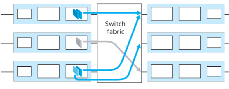
Light blue packet is HOL blocked
- Unlike input queues, output queues can form even when when the packets are not distributed equally among the output ports.
Instead, to ensure no output queueing, you need , which isn’t practical.
So we will almost always have output queuing.
- Active Queue Management (AQM) alhorithms are those that return a congestion notification to the senders when it is likely that the input queue will be overflowing soon. This is done by
- packet marking (explicit)
- packet dropping (implicit)
- Random Early Drop (RED) is a popular AQM algorithm.
- We have 3 different rates to worry about now.
Packet Scheduling
- FIFO : Just one queue
Priority Queuing
- Many classes (Type of Service) of packets each having its own queue.
- The class with more priority gets serviced first.
Weighted Fair Queuing
- multiple classes (TOS) with each having its own queue
- Each class gets assigned a weight .
- For being the set of classes available at the point of decision, the fraction of service that the class will get is for that iteration.
- The “service” is measured in the fraction of time for a time slice that packets will be forwarded from a particular class.
- work-conserving queuing : If a class is missing, skip it in that iteration and go to next class directly. Basically, never be idle. This is automatically because that class will not be in
- Round Robin is just a special case of WFQ where
IPv4 format
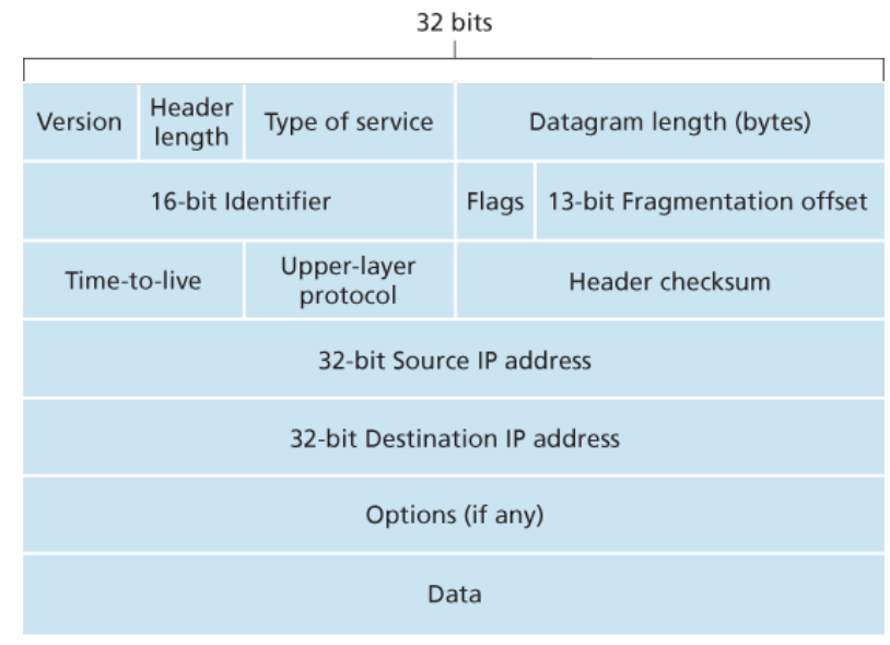
- Version number (4 bits) : Is it IPv or IPv6
- Header length (4 bits) : The options field is variable length so we need to specify the length of the header. Usually it is 20 B only, with no options.
- Type of Service (TOS) (8 bits) : Binary code for what kind of service is the datagram part of, such as
- Real time (IP telephony for example)
- Non-real time (for example FTP)
- Explicit congestion notification
- Datagram length (16 bits) : Number of bytes in the layer 2 segment that this datagram encapsulates.
- Identifier (16 bits) : A segment may be fragmented into multiple datagrams and a datagram into multiple fragments or smaller datagrams (if the MTU is smaller for an output link for example). This field is needed to identify which datagram a fragment belongs to.
- Flags (3 bits) : One of these flags is “last fragment” which is set to 0 for the last fragment of a datagram and 1 otherwise.
- fragmentation offset (13 bits) : Needed to distinguish between fragments for the same datagram and reordering them on the receiver host’s end.
- TTL (8 bits) : This is a number that is decreased every hop. If it reaches 0 before reaching the destination, the datagram is discarded.
- Protocol number (8 bits) : The transport layer protocol that sent this datagram. For TCP, it is 6 and for UDP it is 17.
- Header checksum (16 bits) : The same thing as in UDP, except no pseudoheader involved.
IPv4 fragmentation
The identifier (16 bits), flags (3 bits) and fragmenation offset (13 bits) are used for fragmentation.
Since the Maximum Transmission Unit, which is the size of the link layer frame is different based on different link layer protocols (Ethernet and some WAN having different MTU for example) , so the router must fragment a datagram into smaller ones in case its too big for the output link’s frame.
These fragments are reunited only at the receiver host, and NOT at some router. The routers only forward.
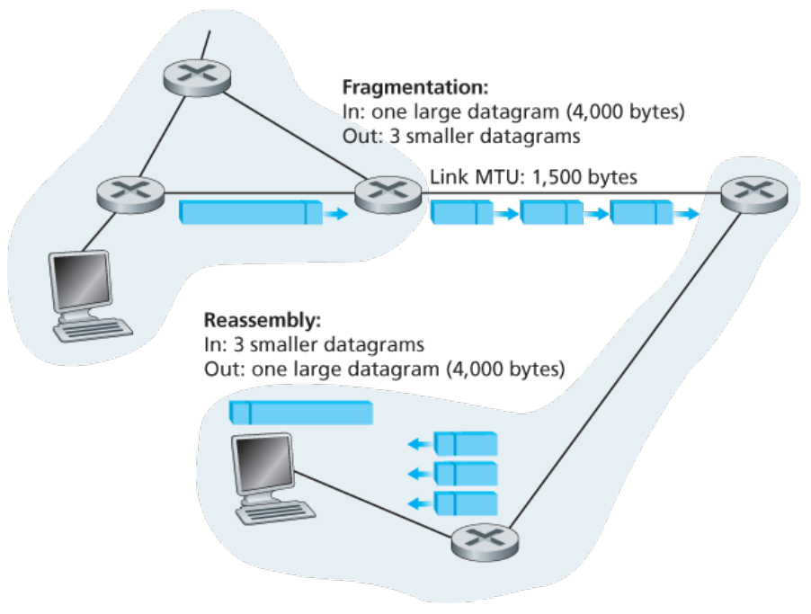
IPv4 addressing
- The boundary between a router and a physical link is called an interface
- IP addresses are actually identifiers for the interfaces rather than the hosts.
- The decimal notation of an IPv4 address is when it’s written as 4 decimal numbers separated by bytes.
The binary notation is just the 32 bits.
- A subnet or IP net is a subgraph of the access network.
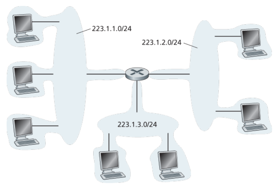
- The leftmost x bits of an IPv4 address are called the subnet address or network prefix or network portion. This is the same for all hosts in a particular subnet. The number x is variable. The IP address is then written as a.b.c.d/x .
- In classful addressing, x is only a multiple of 8.
- if x = 8 : the subnet class is A (largest subnets with 24 bit internal addresses)
- if x = 16 : the subnet class is B
- if x = 24 : the subnet class is C
- Classless Inter-Domain Routing (CIDR) is when x can be anything, not just multiples of 8.
- An ISP is usually assigned an address block corresponding to a particular prefix. For each organisation inside the ISP network, more bits are specified for the network prefix.
- Only the network prefix is used in external routing protocols such as eBGP
- If two BGP speakers are assigned to different ISPs A,B and A acquires B, then the BGP speaker for B can simply advertise the subnet address for A too, in addition to the network address for B. Thus, we have a single prefix for multiple networks. This is called address aggregation or route aggregation.
- The IP address 255.255.255.255 is for IP broadcast across the subnet. Optionally, routers may send this outside the subnet too.
- The Internet Corporation for Assigned Names and Numbers (ICANN) allocates the network prefixes for ISPs .
This organisation also maintains the DNS root servers.
- ICANN assignes addresses to regional internet registeries. All this combined is the Address Supporting Organisation of ICANN (ASO-ICANN)
DHCP
- Inside a subnet, addresses are assigned using the Dynamic Host Configuration Protocol (DHCP). The addresses assigned are intended to be temporary and there is no manual intervention (plug-and-play/zeroconf).
DHCP allows a host to learn
- Its IPv4 address
- The IPv4 address of the local DNS server
- The IPV4 address of the first-hop router (aka default gateway)
DHCP happens in 4 steps
- DHCP discovery
- server offer
- request
- ACK
DHCP discovery
client sends a UDP segment with
- destination port 67
- 0.0.0.0 as source IP address in IP datagram
- 255.255.255.255 as destination IPv4 address in IP datagram
- A transaction ID in the contents of the UDP segment. This ID will be used for all 4 steps.
This datagram is broadcasted to the whole subnet.
DHCP server offers
Any DHCP server in the subnet responds to the DHCP discovery message with another broadcast (hence 255.255.255.255 as destination IP) and its IPv4 address as the source IP.
The offer also contains
- the IP address to assign to the client (
yiaddrr),
- the server ID and
- the transaction ID that the client sent earlier.
- The lease time / lifetime in seconds for which the assigned IP address will be valid (can be hours or days)
- the IP address to assign to the client (
DHCP request
The client chooses one of the offers and echoes back the offer parameters. This is also done in broadcast (255.255.255.255 as destination IP), with 0.0.0.0 as the source IP address.
Since the chosen DHCP server IP is echoed back, the other servers stop the protocol at that instant.
DHCP ACK
The chosen server finally broadcasts an acknowledgement UDP segment, echoing the paramters.
DHCP full flow
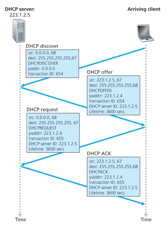
- An issue with Dynamic IP addresses is that it’s impossible to maintain a TCP connection as the client moves.
- CINFO, CHADDR
- DHCP proxy
NAT (NAPT actually)
- The address space 10.0.0.0/8 is one of 3 portions of the full IP address space that is reserved for a private network. Again, the portion we are talking about contains any IP address with 10 as first 8 bits; for example 10.0.0.1 .
- The NAT network addresses are not unique over the gobal internet, but unique in the NAT network
- NAT routers replaces the source ”IP” address for devices in the network and uses its IP address instead.
- NAT routers also replace the source port for outgoing messages according to the NAT translation table
- The NAT translation table maps the source “IP address” and port pair to another source port number which the NAT router replaces the actual source port number with before sending out the datagram.
- For each received datagram, a reverse lookup in the NAT translation table is done to get the actual destination (its NAT network “IP” address) and the actual port.
- Thus, NAT uses port number to address the hosts in the network. This is a violation of the transport layer protocol’s semantics.
This also makes it impossible to have servers in a NAT powered network since they need to have fixed port numbers and thus can’t be addressed using port numbers.
- Public address translation : (src IP a, src port p) → (NAT IP n, src port )
- Private address translation : (NAT IP n, dst port ) → (dst IP a, dst port p)
- In NAT, only addresses are translated to port.
In NAPT, both address and port is translated to the NAT port
- ST-2 protocol was to be IPv5 but the initiative was dropped
- IPv6 was envisioned because IPv4 address space is depleting.
IPv6 format
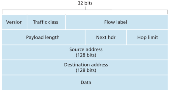
- Traffic class is the same as TOS in IPv4
- Next hdr is the same as protocol feild in IPv4
- Hop limit is just the TTL
- Playload length is an unsigned 16 bit integer giving number of bytes in the playload
- The flow label is an identifier for the flow that this datagram belongs to. A flow is simply a stream of datagrams that when combined, transmit a message; the same as in TCP basically.
Note that IPv6 does not allow for fragmentation.
It also doesn’t do error correction. This is taken care of by TCP or UDP
There is also no option field explicitely present. Instead, the “next hdr” part actually describes the meaning of the next header that will be encountered in the datagram while going up the network stack, and can also be the encoded value for options. So, there are variable size options, but no explicit header length field. Instead, the protocol part is used for that (not the length, just the existence).
IPv6 standard header is 40B .
Tunneling
This is a trick that allows IPv6 speaking routers to talk with IPv4 speaking routers. Basically, the IPv6 router encapsulates the IPv6 datagram into an IPv4 datagram (by adding an IPv4 header). This wrapper datagram is then transmitted by the IPv4 speaking networ until it reaches an IPv6 speakinng router where it is un-encapsulated.
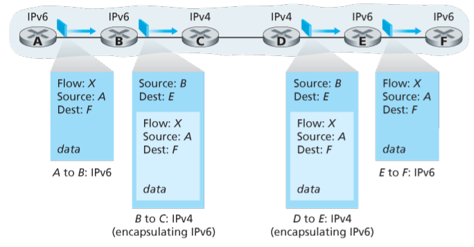
OpenFlow SDN
Here, rather than routers, we deal with generalised packet switches that can do a lot more than forwarding.
OpenFlow is a successful standard that is used for such generalised packet switches.
The forwarding is done by a general match-plus-action principle.
You can match based on information from transport, network and link layer rather than just the network layer like in a router.

For actions, you can do
- forwarding to a particular output port
- broadcast over all ports
- Encapsulate the packet ant send to the remote controller
- Drop the packet (default action, if nothing specified in flow table)
- Modify any of the feilds for layers 2,3,4; except for the IP
protocol/next hdrfeild.
The match-action pairs make up the flow table for the packet switch.
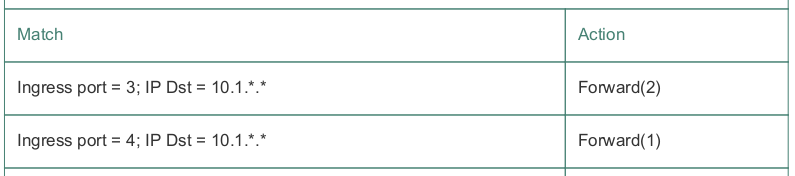
The flow tables are in-turn updated by the remote controller that runs on software, rather than hardware like the packet switches.
Thus, the flow tables are like API for the packet switch that the remote controller uses to program.
Just like modern routers, an OpenFlow devices uses TCAM for the matching.
Chapter 5
per-router vs logically centralised
- per-router control is when the routing algorithm runs in the routing processor rather than a remote controller. Examples : BGP, OSPF
- Logically centralised control is when it the routing algorithm runs is a central remote controller. Example : OpenFlow and SDN
Control Agent
A control agent (CA) is a part of the router whose job is to communicate with the central controller.
CAs don’t interact with each other and don’t actually compute forwarding tables.
Infinity weight trick
When two routers are not connected directly by a communication link (i.e. ), we can model that as where is the cost function.
Centralised and Decentralised routing algorithms
- A centralised routing algorithm is one where all the information about the graph is known beforehand and then the routes are computed. Basically, you need to be aware of the states in which the links are, hence “Link State” (LS) algorithms.
- A decentralised routing algorithm is one where the changes in routes in response to new local information are done locally. The calculation is thus distributed and iterative. The full link state information is not known. Only the previously computed distances from a given node to other are known at a particular node; namely the distance vector (DV) .
static vs dynamic
A static routing algorithm changes the routes very slowly (mostly due to human intervention) as opposed to a dynamic routing algorithm that changes it fast.
In a load sensitive algorithm …
the link costs change as a function of the flow.
Link-State algorithm
- Since so, to find the shortest paths to any node, the LS approach is for all routers to flood the LS information, and the for all routers to individually run Dikstra’s or Prim’s shortest path algorithms to computer their own forwarding tables. This works well for load insenisitive networks, but not for our case.
- A solution is to have only one router update its forwarding table at a time, and flooding the network with LS information again after that.
- An issue with this is something known as Floyd Synchronisation, which is a tendency of the routers to synchronise on their own.
Bellerman-Ford equation
Let be the smallest path distance from node to . Then, the Bellerman-Ford equation says that
Using this, we can set up an iterative solution.
Let be the known smallest distance from to by the node .
DV algorithm
-
- loop :
- for :
- if changed in last iteration for any :
- for :
-
- for :
- if changed in last iteration for any :
- for :
-
- for :
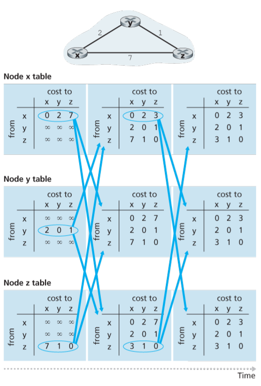
count-to-infinity
The DV algorthm suffers from this issue.
Suppose you have the network described in this picture :

The DV algorithm has reached an equilibrium where z is routing to x through the interface towards y.
Now, suppose the changes from 4 to 60, then will first try to re-compute . This will fail since is 5, making . Then, will update after sends it the distance vector and then update . Later, we will get and so on. This will keep on going till we eventually reach and .
Poisoned reverse
To avoid this extremely slow convergence due to the count-to-infinity issue, we should use poisoned distance reverse. Basically, if for the smallest path to a node , some node is going through a node , then should tell that even though it isn’t.
Another way of saying this is that tells to not route through it to reach ; hence the distance.Unfortunately, this isn’t enough.
Consider this network :
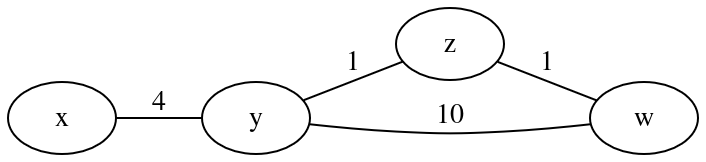
You will have a loop between and now when changes to 60 suddenly.
Autonomous Systems
- An autonomous system (AS) is a network where all routers speak the same routing protocol and form a connected component for that protocol.
- An AS can contain multiple sub-nets.
- Every AS gets an Autonomous System Number (ASN) assigned by ICANN.
OSPF
- Open Shortest Path First
- This is an intra-AS routing algorithm.
- This uses LS brodcasting and then Dijsktra’s algorithm in each router (classic LS strategy)
- The broadcasts happen periodically regardless of whether the LS info for a certain router has changed.
- OSPF adverticements are carried directly using IP
- OSPF is actually treated as a transport layer protocol by IP, and is assigned the protocol number 89
- OSPF implements reliable message tranfer and link state broadcast
- OSPF routers additionally check if the attached links are active by sending a HELLO message to the neighbourhood routers.
- Exchanges between routers can also be authenticated in OSPF allowing only trusted routers to run this protocol.
- OSPF authentication can either be done is plaintext (simple mode) or with MD5 encryption (MD5 mode)
- When a router multiple paths to another node with the same distances, then both paths can be used (using RR for the traffic, for example)
- Multicast OSPF (MOSPF) is an extension over normal OSPF (which is already multicast btw)
OSPF also allows for heirarchy
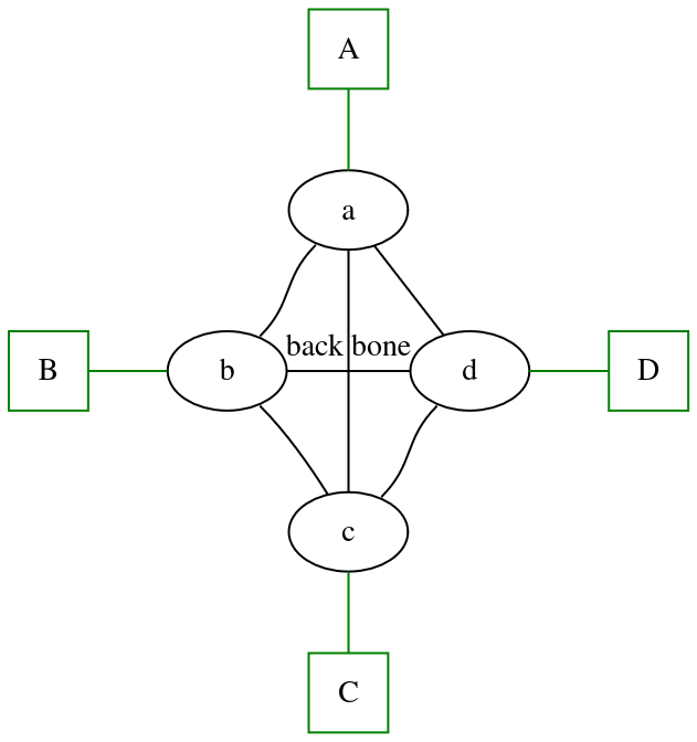
code
graph G {
    rankdir=TD
    A [shape=square color=green]
    B [shape=square color=green]
    C [shape=square color=green]
    D [shape=square color=green]

    A -- a [color=green]
    c -- C [color=green]
    a -- d
    a:sw -- b:ne
    d:sw -- c:ne
    b:se -- c
    a:s -- c:n
    subgraph{
        rank=same;
        B--b [color=green];
    }
    subgraph{
        rank=same;
        d--D [color=green];
    }
    subgraph{
        rank=same;
        b--d [label="back bone"];
    }
}
You can split the AS into a bunch of areas, with each area having some area border routers and the normal routers.
The area border routers are all connected to a back-bone area which routes traffic between different areas.
The back-bone must contain all area border routers, and hence no peering between the areas; everything passes through the backbone.
The back-bone may also contain non-border routers too.
BGP
- Multiple subnets are handled by a single BGP speaker.
- BGP speakers communicate over TCP
- When two communicating BGP speakers are part of the the same AS, it’s called an iinternal BGP (iBGP) connection. Otherwise, external BGP (eBGP).
For the remaining portion, consider this network :
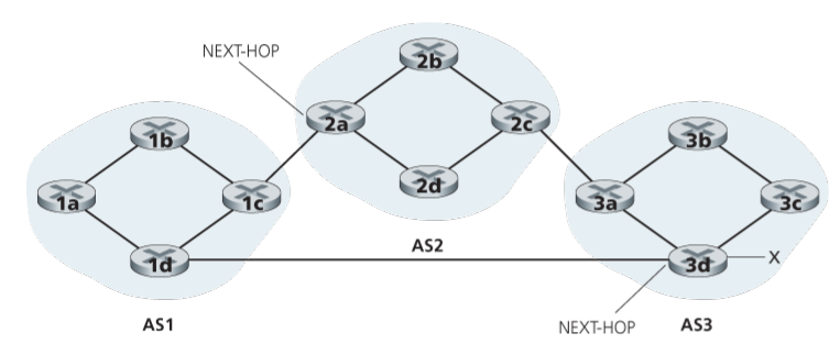
- x is the network prefix of a subnet that is newly added. We want its existence to be known to the whole world.
- The BGP speaker 3d tells and 3a,3c through iBGP about the existence of this prefix. This is iBGP. 3a and 3b tell 3b then. The message that is passed can be denoted as simply
xfor now.
- 3d tells 1d through eBGP of the existence of x . This is done via the message
3d AS3 xwhich reads “x exists, and it can via the AS path with only AS3 in it. To start the path, hop to 3d” . Similarly, 3a sends3a AS3 xto 2c
- 1d propagates the
3d AS3 xmessage throughout AS1 using iBGP. Thus, all the BGP speakers in AS1 will now route packets to x through 3d (the next hop router).
- 2c propagates the
3a AS3 xmessage in AS2 using iBGP .
- 2a sends 1c the eBGP message
2a AS2 AS3 xwhich reads “x exists and can be reached by the AS path AS2,AS3 . To start the path hop to 2a (me)”.
- 1c propagates the
2a AS2 AS3 xmessage through iBGP to all of AS1 . Now, the routers in AS1 must decide which route to choose. Route selection is done based on these factors in decreasing priority- local (ISP) preference (biggest priority)
- length of AS path (
AS2 AS3vsAS3).
- length of path to next-hop router (
2avs3d) . This is called hot-potato routing.
- BGP identifiers
In this case, assuming local preference allows both routes, the
3d AS3 xroute will be chosen as it has smaller AS-PATH
- AS-PATH, a sequence of the ASNs for the ASs in the path is a BGP attribute
- Similarly, NEXT-HOP, the IP address of the next-hop router is a BGP attribute
- A BGP route consists of the network prefix and several BGP attributes; AS-PATH and NEXT-HOP being two very important ones.
- Once a BGP route is selected by a router, it uses its forwarding table to learn which interface does the NEXT-HOP value get mapped to. Then, it inserts the network prefix and this interface as a pair in the forwarding table
IP anycast
The DNS root servers for a particular DNS root server organisation (out of the 13 that there are) all have the same IP address. For example,
8.8.8.8is an IP address for many physical DNS servers, all of which virtually/logically appear to be a single entity.To make this happen, we need multiple subnets; potentially in different ASs; that have the same subnet address (prefix).
In such a scenario, when these subnets are advertised and any BGP speaker gets two routes; each originating from a different subnet, but having the same prefix; then these routes are simply treated as multiple paths to the same destination. The BGP route selection protocol operates as usual, and the “best” route is selected; and thus, the “best” subnet, without the BGP speaker having any idea about the existence of multiple subnets with the same prefix.
Role of policies
The ISP can have a policy for example, to only route traffic with a customer or domestic sub-net as source or destination, and not allow free-riding.
So, when it gets a BGP advertisement from a subnet that is not a customer, it will gladly spread it via iBGP but not through eBGP since that’s basically telling other ASs “hey, look at this route to this subnet that I don’t server. I can take you to this subnet. Just hop on the NEXT-HOP router that is inside my network. I’m a very altruistic ISP and I don’t care about all the extra link utilisation, traffic intensity and packet loss that routing your traffic through my network will cost me.” .. you get the point, right ?
SDN
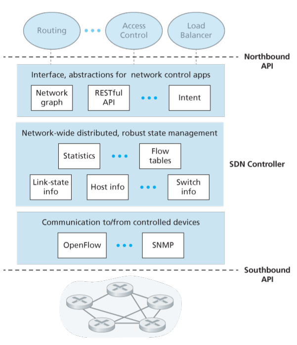
SDN controller The controller acquires information from the controlled devices using protocols such as OpenFlow and SNMP. This is south-bound API
The state management layer is where information from multiple of the SDN controllers are combined.
The API through which the controller interacts with the applications that actually do stuff, such as running the Dijkstra’s algorithm for example, are called the Northbound API. This can be a graph database, or REST, or anything really.
OpenFlow
- A southbound API
- Runs on TCP port 6653
The types of messages that can be sent from the controller to the switch are:
- Configuration (”switch, please set these parameters”)
- Modify-State (”switch, update your flow table to this”)
- Read-State (”switch, read and send your flow table’s statistics and counters”)
- Send-Packet (”switch, send this specific packet from this specific output port”)
The messages that can be sent from switch to controller are
- Flow-Removed (An entry in the flow table has been removed)
- Port-Status (An output port has shut down or is malfunctioning)
- Packet-In (I didn’t have a match for the address in this packet, help me)
ICMP
- Internet Control Message Protocol
- This is for the communication between routers as opposed to through them.
- ICMP messages are encapsulated in IP datagrams with port number of 1
- Each ICMP message has a type number and code number.
- Each ICMP message contains the first 64 bits (first two lines) of the IP datagram that triggered this message.
ICMP messages
type code Description 3 0 destination network unreachable 3 1 destination host unreachable 3 2 destination protocol unreachable 3 3 destination port unreachable 3 6 destination network unknown 3 7 destination host unknown 4 0 source quench (congestion control) 0 0 echo reply (to ping for example) 8 0 echo request (like in ping) 9 0 router advertisement 10 0 router discovery 11 0 TTL expired (like in traceroute) 12 0 IP header bad
- ICMP was designed for IPv4. With IPv6, they have added more messages, such as “Packet too big” since IPv6 doesn’t have fragmentation and “unrecognised IPv6 options”.
SNMP
- Simple Network Management Protocol
- This is a protocol used by (human) network administrators to debug network issues.
The key components of network management are:
- The managing server (usually with a human in the loop) running in a Network Operations Center (NOC).
- The managed devices and managed objects (hardware or software parameters) inside it.
- The management information base (MIB), which is a store of several managed objects/parameters (such as counters, descriptive information, routing path to a destination, etc.) inside a managed device.
- The network management agent (basically CA for SNMP) is a process running in the managed device that communicates with the server.
- The network management protocol allows the management agent and server to communicate.
- MIB objects are specified using a data description language called Structure of Management Information (SMI) .
- Related MIB objects are gathered into MIB modules.
- SNMP usually runs in a request-response mode where the server first sends a request (to query or modify MIB objects) to the agent which then performs some action and sends back a response.
- When the agent sends the server a message by itself to inform about an exceptional event that has occured, it’s called a trap message.
- SNMPv2 messages are simply called PDUs (protocol data units).
- A manager can also ask another manager for information.
Different PDU types
- The
GetRequest,GetNextRequestandGetBulkRequestquery PDUs are sent from manager to agent (or another manager) to query for MIB vales.
- The
SetRequestPDU is sent from manager to agent (or another manager) to set a bunch of MIB objects.
- A
ResponsePDU is sent from an agent to manager in response to a query orSetRequestPDU.
- The
InformRequestPDU is sent by a manager A to another manager B in response to a query orSetRequestsent by B to A.
- Finally, there are
SNMPv2-TrapPDUs sent by agents to manager when exceptional events occur.
- The
- The lack of security made SNMPv1 a monitoring protocol rather than a control protocol (rendering the modification part obselete)
- SNMPv3 focuses heavily on security.
Lec 1,2
Key design principles for internet architecture
- Robustness :
Be conservative while sending , and liberal while accepting
- Layering principle :
The message on system A’s layer N will be transmitted to system B’s layer N, as it is with no modifications. All the stuff done by the lower layers must be removed by B .
- End2End :
The actual computation only happens on the end systems.
- Network is stateless
Only the end systems manage state.
- Robustness :
Why layering ?
- modularity
- reduced complexity for writing code
- more flexibility in modifying the higher level modules and thus the computer networks
- standardised interfaces makes development easier
- functionality reuse :
A common functionality of a lower layer can be shared by many upper layers
- Adaptability :
Mix and match functionalities across different layers.
Incremental changes are easier to make and accumulate
- modularity
peer layer
Same level layers in end systems that are communicating
vertical communication
The communication between adjacent layers on just one end system. Like, between application layer and the transport layer.
horizontal communication
Virtual communication between peer layers.
Protocol layering
“This is the grouping of communication functions into heirarchial set of layers.”
- every layer has a different subset of functions
- every layer relies on the lower layers for more primitive functions
- every layer provides service to the higher layers
- Implements a protocol for communication with peer layers (horizontal communication)
SDU
Service Data Unit
This is an input of any protocol for a certain layer.
PDU
Protocol Data Unit
This is the output of the protocol for a layer.
This is basically the SDU, with a header attached at the front, for the layer protocol in a network application.
The horizontal communication between peer layer entities (processes for that layer) happen happen by exchange of the PDUs (virtually)
Note that layer N does NOT make use of .
Protocol
The set of rules that govern data communication between peer layer entities
Encapsulation
The PDU for a layer contains all the information that will be needed for the upper layers to comprehend it. That is, it encapsulates the information and now we can think of it as “just data” in the lower layers.
Lec 3
- Bandwidth is the maximum throughput through a link (the maximum transmission rate).
- Throughput is the actual transmission rate observed through a link bits per second.
- Goodput is the rate of transfer of application layer messages (in bits per second) . Basically Goodput is measured discounting the headers.
Plus, the data lost due to packet loss is also not “useful” data so it’s not to be included while calculating goodput.
- “link capacity” = “link bandwidth” = “link transmission rate” .
- The transmission delay is the size of packet divided by the throughput (NOT the bandwidth).
- When there’s one router between two devices the transmission delay is
- “Cut through” is when you don’t want to do store and forward. Instead, you store till you have the destination MAC address (6 bytes), then compute the output link and start transmitting without storing.
This doesn’t allow reliable transmission since you aren’t able to store and compute to see if the data is correct (using Hamming codes or whatever). While in store-and-forward, the transmission would just stop at the first router where eronnous data is encountered, in cut-through, the data is forwarded.
To somewhat solve this, you can store extra 64 bytes for figuring out if there is an error (using checksum or something)
- CFS (completely fair scheduler) was built for networks and later cam to linux kernel. This aims to reduce the response time.
Lec 4
- Ingress link is “Incoming” link.
- The Egress link is “outgoing” link.
- The first thing that happens when a packet reaches a outer is the ingress processing.
- There CAN be queuing delay at the source. This happens when we are transmitting only once all packets are prepared.
- read a bit about sequence diagrams in the context of delays
- Ingress processing can happen even when egress processing is going on. Basically, there is some pipelining in a router.
- Practice end to end delay questions, a LOT.
- We have two kinds of throughput : instantenous (used for identifying peak bit rate (PBR)), which is measured over a small window and average throughput, that is measured over a longer window.
Lec 1-5
Switching techniques
Message switching
This is similar to packet switching except that you send the full thing all at once, with no packetisation.
There is also resource reservation on the routers (similar to that in circuit switching).
For example, telegram messages were transmitted like this.
This also uses store and forward architecture.
- Circuit switching is “cut-through” (just the opposite of store-and-forward)
CDM
Similar to TDM and FDM, there is code-division-multiplexing. In this, you encode 1 as some vector and 0 as for each connection. Now, we want all these vectors to be orthogonal, so that you can do superposition and transmit the resultat vector. That vector will be decomposed at the reciever end, with no loss in information.
- Wavelength-Division-Multiplexing is just FDM but in fiber optics.
- Synchronous TDM is when there is a proper RR scheme
- Statistical TDM is when the sender only transmits when it is ready. This happens in Ethernet.
- Ingress is incoming and egress is outgoing data
Organisation names
- IEEE : Institute of Electrical and Electronical Engineers
Manages Data link and Physical layers
- IETF : Internet Engineering Task Force
Manages Network and Transport layer (IP/TCP) and RFCs
- W3C : World Wide Web Consortium
Manages application layer protocols
- ISO : International Organisation for Standardisation
Maintains other standards. A bit outdated.
- ITU : International Telecommunication Union
Manages protocols related to telecommunication
- IEEE : Institute of Electrical and Electronical Engineers
Overview Slides
- A computer network is an infrastructure that facilitates communication across devices.
The infrastructure encompasses hosts, switches and the medium too.
unit prefixes
Name Symbol Value kilobinary Ki 2^10 kilo K 10^3 megabinary Mi 2^20 mega M 10^6 gigabinary Gi 2^30 giga G 10^9 terabinary Ti 2^40 tera T 1000^4 petabinary Pi 2^50 peta P 1000^5 exabinary Ei 2^60 exa E 1000^6 zetta Z 1000^7 yotta Y 1000^8
Internet is big endian
meaning that the address of a word is the byte addess of the MSB in the word. For little endian, it is the LSB.
3 aspects of protocols
- syntax (data format and physical modulation)
- semantics (procedure for communication)
- sequence (frequency and order)
Principles of internet architecture
robustness principle
Be conservative in what you send and liberal in what you accept
Layering principle
layer N PDU on receiving side is transmitted exactly the same when it reaches layer N on the other side.
End2End principle
Network is stateless (dumb) and hosts manage states (intelligent)
Why layering
- Modularity allows for
- reduced complexity when focusing on smaller problems
- more flexibility
- standardised interfaces
- functionality reuse (a service provided by a lower layer protocol can be used by multiple higher layer protocols)
- Adaptability
- Easier incremental changes
- Modularity allows for
Encapsulation
The control (header) information added to the SDU to produce the PDU has all the necessary information for to be used as (and thus, be the payload now).
Thus the PDU encapsulates the SDU and the control information.
Peer processes
Peer processes are those running on the same network layer on different devices that are communicating.
SAP
Any layer’s service can be accessed through its Service Access Points
- Ethernet operates on 10Mbps to 100Gpbs
- Fibre optic operates on 10Gbps to 100Gbps
- Link capacity is just bandwidth
International Organisations
IEEE
- Institute of Electrical and Electronics Engineers
- Data link layer
- Physical layer
IETF
- Internet Engineering Task Force
- Network layer
- Transport layer
- Request for comments (RFC)
W3C
- World Wide Web consortium
- Application layer
ISO
- International Organisation of Standardisation
- Open systems interconnection (OSI)
- All layers
ITU
- International Telecommunication Union
- All layers
Application Layer Slides
IPC
Inter-Process-Communication
- Through the files (disk)
- Through PIPE (not storing to an actual file, but rather passing chunks directly to next process in RAM itself)
- FIFO channels are persistent named channels that are stored in the file system. This is similar to PIPE, except they allow communication between unrelated processes. Note that the actual data only goes through RAM, never through the disk.
- Mailbox is a shared data structure where one process can write a message and another can read it, similar to the buffers you usually have in a producer-consumer problem.
- Shared memory (RAM) is another easy way for IPC. This is a block of RAM that is in the address space of both the processes.
- Message passing is what the mailbox DS allows.
- In the client-server app. arch. , the server is by-definition, always on and has a static IP address.
P2P characteristics
- no always-on server
- self scalibility’
- complex management
Generic Requirements for application layer protocols
Read that again. It’s the requirement, not the service. The requirements are in fact services provided by transport layer protocols.
- data integrity (reliable data transfer)
- timing (guarantees on delay)
- throughput
- Instantaneous Throughput insensitive apps are called “elastic”.
- Securiy
- There’s this thing called SSL that only exists for that one purpose.
FTP (RFC 959)
- The client first connects to the server on port 21.
- The client is then authorised using username and password.
- Just using port 21 TCP connection the client can navigate the filesystem already. This TCP connection is called the “TCP control connection” .
- To receive a file, the server opens a second non-persistent TCP connection through port 20, called the “TCP data connection” .
When the transmission is done, this connection is closed.
- The server has to maintain the state for each connection (current directory, authentication, etc.)
- In networking, when data and control share the same connection, it’s called in-band. So FTP control connection is “out-of-band” .
The client is made up of 3 parts :
- Application interface (GUI or shell)
- The Protocol Interpreter (PI) , which interprets the FTP commands coming from above and replies coming from the server’s PI.
- The Data Transfer Process (DTP) which only handles data transfer.
The server process has 2 parts:
- The Protocol Interpreter (PI) which interprets commands, makes changes in state (variables) and sends responses.
- The Data Transfer Process (DTP) which handles data transfer
- Although DTP is called “process”, it’s actually not a separate process in the OS sense, just in the logic sense.
- FTP command are sent as ASCII text
FTP commands
- USER <username>
- PASS <password>
If no password is needed, you may skip that field.
- LIST [<directory>]
lists file in current directory or one given
- RETR <filename>
Downloads a file
- STOR <filename>
Uploads a file
- DELE <filename>
Deletes a file
- CWD <directory>
Changes current working directory
- MKD <directory>
- RMD <directory>
- PWD
Prints working directory
- CDUP
Changes to parent directory.
- QUIT
- HELP [<command>]
Shows help in general or for specific command.
FTP return codes
331Username Ok, password required
125data connection already open; transfer starting
425Can’t open data connection
425Error writing file
Can you transfer executables via FTP ?
Yes, you can.
There are two transfer modes, ASCII mode, which is unsafe for executables and images since it converts line endings between systems (\r\nvs\n) , and the binary transfer mode which doesn’t do that.You can change the mode using the
TYPEcommand. By default, it is ASCII. You can set it to binary usingTYPE I(whereIstands for “Image”)
- PTP and MTP are transfer protocols for Photos and Media.
- Since FTP transmits data in cleartext, it was removed from the FireFox browser on July 13, 2021
FTPS
To make FTP more secure, you can use SSL/TLS rather than simple TCP. This leads to what is called as the FTP-Secure protocol.
It’s used by .NET
SFTP
Another method is to use SSH to do file transfer, rather than FTP. This leads to the SSH-File Transfer Protocol.
Sometimes it’s also called the Secure File Transfer Protocol.
Note that this is NOT just FTP over SSH, but a whole new protocol.
TFTP
The Trivial File Transfer Protocol is an extremely simple protocol that does no authentication, no encryption, no directory listing or navigation. It provides only read/write capability.
This is used for embedded devices, network boost, routers, and other non-computer-like devices.
- Uniform Resource Locator (URL) is the address of an object
- Uniform Resource Identifier (URI) is just an identifier. It doesn’t locate the object.
- All URLs are URIs but not the opposite.
- HTTP is stateless
Server maintains no info about client history (except cookies and stuff, but that’s just people extending it).
HTTP methods
- GET (was there in HTTP/0.9)
- HEAD (HTTP/1.0)
Just gets the status line and header
- POST (1.0)
Puts name,value pairs in body of request message
- PUT (1.1)
Uploads the object (data in message) to the given URL on server
- OPTIONS (1.1)
Get the information about what actions (methods) are available on a particular resource (URL). This info is put in the “Allow” header in the response message.
- DELETE (1.1)
Deletes the file with the specified URL
- TRACE (1.1)
It’s for debugging purposes. It lets the client see if any proxies or gateways are modifying the request.
- CONNECT (1.1)
This is used to create a network tunnel through a proxy to another server. Basically, the client sends the CONNECT request to the proxy with the host being the target server. The proxy than creates a connection to the target and forwards messages from client to the server, without looking at them.
- PATCH (1.1)
Partially updates an object, unlike PUT which replaces the full thing.
HTTP response status and phrase
- 200 Ok : request succeeded.
- 301 Moved Permanently : File not at URL. New location is specified in the location header
- 304 Not Modified : Response to conditional GET
- 400 Bad Request : Parse error
- 401 Unauthorised : Wrong or missing authentication
- 404 Not Found : Nothing found on the URL.
Idempotent, Safe, Cacheable
Method Type TRACE Safe OPTIONS Safe GET Cacheable HEAD Cacheable PUT Idempotent DELETE Idempotent POST Not Idempotent PATCH Not Idempotent CONNECT Not Idempotent The reason TRACE and OPTIONS are safe but not cacheable is because it would be wasteful.
- URL length in HTTP message is 2048 characters.
- Since GET uses URL to pass variables, it has a limit on amount of variables it can pass. Meanwhile, POST uses the message body and has no limit.
- HTTP is stateless, i.e. the current request output doesn’t depend on past requests.
- HTTP is not sessionless. It does keep some information about the type and credentials of user in cookie files.
- Third party cookies are cookies set by other websites that are tracking your actions on the website you are currently on.
- “Second party cookies” are not a thing. Informally, it’s when a company shares its data with another party rather than have the other party track the users’ actions through third party cookies.
- Only ASCII characters are allowed in GET (since it’s encoded in URL), while even binary data is allowed in POST.
- GET should NOT be used for login. The recommended method is POST.
- Just as POST requests can’t be cached, neither can a POST response (page) be bookmarked.
Uses of cookies
- authorisation (login)
- maintaining session state across logins (think, web e-mail and shopping carts)
- Tracking (google does this). Helps them place ads.
- Personalisation (meta does this)
- In guest mode, cookies are temporary and are deleted when you close the tab/session
Head-of-Line (HOL) Issue.
- in HTTP/1.1 pipelined requests, the objects would be arranged serially on the TCP connection. Now, if one TCP segment is lost for a particular object, the other objects too would have to be retrasmitted (assuming no buffering of out-of-order packets)
- In HTTP/2.0 the objects are interleaved on the connection. So if there’s a packet drop, some data for each object has still arrived. Using SVD and other things, you can make web-pages still appear to have loaded.
- In HTTP/3.0, rather than using TCP, we use QUIC, which doesn’t face this issue.
HTTP/3.0 also allows UDP by the way…
Conditional GET contribution to average page load time
The textbook uses a model of web-caching where conditional GET doesn’t happen, when solving problems even though they detail the process differently. This is because in real life, the conditional GET is only done periodically.
For a conditional GET, the responses can be:
304 Not Modifiedstatus and no data
200 OKand the object requested.
HTTP 0.9
- No headers
- GET was the only method
- No status codes
- No “version” field (obv)
HTTP 1.0
- HEAD and POST methods
- headers
- version
- status code
- more content types
HTTP 1.1
- remaining 6 methods (PATCH,CONNECT,TRACE,OPTIONS,PUT,DELETE)
- Persistent and Pipelined connections
- Longer lived connections
- Chunked transfers
SPDY
- Server push
- Binary Framing layer
HTTP 2.0
- a solution to HOL blocking
HTTP 3.0
- Ditched TCP to go for QUIC. This is a transport layer protocol which runs over UDP .. yes, a layer 3 proto. over another layer 3 proto. Well, it is what it is.
- Enhanced privacy and improved performance
SMTP
- Simple Mail Transfer Protocol
- First RTT for TCP connection
- In Second RTT, server states it’s ready with status code 220
- In Third RTT, the client sends a HELO or EHLO and gets a reply from the server (expected is “250 Hello…”)
- Finally, the client asserts it’s going to send mails using MAIL-FROM and RCPT-TO and DATA. When given an ok signal from the server, it sends the mail and ends with a “.” .
- Uses 7 bit ASCII
- Persistent TCP connections
- port 25 , 587 or 2525
- Mail syntax is headers (”From”,”To”,”Subject”,”Date”,etc.), a blank line, data and “.” .
- push protocol
- Mail server rotates mails and sends a response to the browser it was unable to send after a timeout.
IMAP
- Internet Message Access Protocol
- 7 bit ASCII
- Folder structure
- Keeps the mail on the server
DNS
- Domain Name System (the system/service and the protocol)
- distributed database
- CNAME, NS and MX type RRs map names to names. Only A and AAAA map names to IP address
- The logical hostname in a FQDN is the first component.
13 root name server companies
- 10 in USA
- 1 in Netherlands
- 1 in Sweden
- 1 in Japan (this is where RR for
inTLD is stored)
- The actual number of root name servers are over 1000
- NIXI, an indian organisation manages 54 root name servers, located in multiple cities.
- Network Solutions maintains the
.comTLD servers
- Educause maintains
.eduTLD servers
- All local servers know the root servers. (Their IP addresses are stored in a local configuration file).
- DNS uses TCP as a fallback if message length is too big
- To set up a new hostname on DNS, you need to register it at a DNS registrar
registery.infor example, is a DNS registrar.
- There are more than 1000 registrars worldwide.
DNS syntax
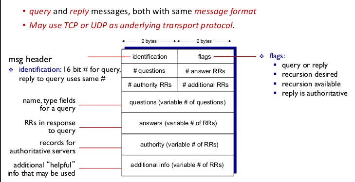
6 header fields, each of 2 byte:
- id
- flags
- no. of questions
- no. of asnwers
- no. of authoritative RRs
- no. of additional RRs
- Question section has (name,type) tuples.
- Other 3 sections have full RRs.
- Full domain name must be strictly less than 256 characters
- Each component of the domain name must be strictly less than 64 characters
- Only alphabets, numbers, and hyphens are allowed in the components
- DNS is case insensitive.
TTL in DNS
This is NOT in the TTL for IP datagrams. Instead, it’s the time for which a RR can be cached by a server that isn’t authoritative for it.
This is done to avoid out-of-date address translation.
Projects
- Quantum Networks (1.25)
- Instead of a classical stack, there’s a quantum stack.
- IP layer, but using quantum computing
- Create a routing algorithm
- Implement on simulators
- Reference paper. Implement the result and then your own.
- Quantum BGP
- Paper is there. Implement on simulator
- Validation and benchmarking
- IP layer
- Understanding host network stack.
- SDN based routing
- Open source blitzping
- traceroute like thing
- uses dpkd rather than native socket API
- IPv6 Routers using P4 programming language (5) (1.8)
- Simulation tools like MiniNet
- Distributed Network File System
- Caching on client side
- Already done…
- Network telementary
- Monitor routers in real time
- SNMP
- Network congestion control simulator
- Educational tool
- DNS query and resolving visualiser
- Educational tool
- Pre-process bandwidth tracker using eBPF
- real time
- Learn eBPF
- Packet drop logger using eBPF
- Southbound communication (SDN) using UDP rather than TCP
- Securing southbound communication using Post-Quantum cryptography algorithms (6) (1.8)
- MCP server and AI
- MCP based protocol (DASH, SFTP, etc.) selection (2.15)
- Multi path TCP and QUIC metric comparison
5G stuff …
Oct 10
RDT is
- (packet) loss free
- error (corruption) free
- in-order
Oct 14
- Silly Window Syndrome : The receiver advertises a small window size and the sender send segments of that (less than MSS). This causes the TCP/IP headers to dominate, wasting bandwidth.
- Clark’s Solution (ACK with-holding) : The receiver should only ACK when the receiver window size is more than a fixed amount (1 MSS or the half the buffer size)
- Tinygram syndrome : The application layer on the sender’s side only generates data in very small segments (think, an interactive terminal). This again, causes the TCP/IP headers to dominate.
- Neagle’s solution : The sender should buffer data that comes from the application layer into the TCP buffer till a certain size is reached.
Transport Layer Slides
UDP data format
- src port (16 bits)
- dest port (16 bits)
- length (16 bits)
- checksum (16 bits)
Wrap-around binary addition
Consider the 4 bit numbers 1101 and 1010 . Adding these two gives sum of 0111 and c-out of 1; basically 10111 . Now, we can wrap-around the c-out back to the units place giving us 0111 + 1 = 1000 as the wrap-around sum. Denote by the wrap-around sum. Then, for and , you have .
IP Pseudo-header
- 32 bit srcIP
- 32 bit destIP
- 16 bit Datagram Length
- 8 bit Upper layer Protocol code
- 8 bit of padding
Checksum
- Create the UDP segment, with UDP checksum set to 0
- Add the IP pseudo-header to the segment
- chunk into 16 bit words
- Wrap-around binary add the 16-bit words
- Take one’s complement of the sum.
TCP segment structure
ports (32 bits)
- 16 bit src port
- 16 bit dest port
- 32 bit seq. no.
- 32 bit ack. no
- 4 bit header length (number of 32 bit words in the full TCP header)
- 4 bit reserved
Flags (8 bits)
- CWR
- ECN/ECE
- URG
- ACK
- PSH
- RST
- SYN
- FIN
- 16 bit Recieve Window Size
- 16 bit Urgent Pointer
- 16 bit Checksum
Problem with 2-way handshake
- server won’t have a good estimate for RTO
- SYN packet flooding is easy for the client since client doesn’t need to allocate resources or wait.
RFC 793 “Duplicate packets from previous connection” (Fals/ Half-open connections)
Suppose the client retransmits the SYN one time, giving us two SYN packets on the wire. The first one reachers the server and the server allocates resources. Now, when the second one reachers the server; in the eyes of the server there are two things that could’ve happended :
- The client didn’t get the first ACK back and retransmitted (the actual reason)
- The client closed the connection and after some time (MSL), started a new connection.
Note that the server will have this confusion regardless of how far apart the two SYNs are, since the RTO can grow arbitrarily large; and there can be multiple retransmissions 1,2,3…n for the SYN; with only the first and last (nth) SYN reaching the server.
TCP client connection closing
- FIN_WAIT_1 : FIN is sent and we will wait RTO for ACK. We have also deleted the send-buffer. So, we can only recieve now.
- FIN_WAIT_2 : ACK from server is recieved. Now, we must wait for server to finish and send the FIN.
- TIME_WAIT : FIN is recieved and ACK is sent back. We will keep sending back ACKs for any FINs we recieve for the next 2*MSL time.
- CLOSE : After 2*MSL , we have deleted the recieve buffer too.
TCP server connection closing
- CLOSE_WAIT :
- FIN arrived from client
- ACK returned in response.
- closed the reciever buffer.
- LAST_ACK :
- Send buffer closed
- FIN is sent
- CLOSED :
- ACK is recieved.
- CLOSE_WAIT :
3 D-ACK
When sender recieves 3 dup-ACKs; thus, in total 4 ACKs with same acknowledgement number, then it will retransmit exactly one segment and stop the timer.
The number “3” is chosen mostly based on ad-hoc reasoning and data analysis.
D-ACK retransmit suffers from un-ordering of segments, in which case the later segments that arrive too early are either discarded or buffered, and duplicate ACKs are sent in return.
The higher the threshold for D-ACK count, the more is small un-ordering allowed.
Silly Window Syndrome
When the reciever has less than 1MSS of window left and it sends ACK also asking to sent the
rwndto that size, the sender will start sending data with segments of that size (< 1MSS). The same amount of data will be consumed by the application and the cycle will continue.This is problematic because the TCP/IP headers dominate the actual data on wire; thus decreasing the goodput.
A partial solution is ACK witholding
Tinygram Syndrome
Here the sender itself is sending segments with very little data (tinygrams). This is not because the reciever has a small buffer space left at any moment, but because the appication at the sender is sending data as soon as it is produced.
For example, remote terminals sending 1B of payload every segment.
This again, leader to the stream being dominated by headers. To solve this, ACK witholding at the reciever’s end won’t work (it will cause error on sender’s side).
Neagle’s solution : Instead, the sender should buffer the data till it becomes enough to fill 1 MSS.
This is actually implemented in TCP and can be disabled using TCP-NODELAY option.
TCP initial
cwndvalueMSS (B) cwnd (MSS) (0,1095] 4 (1095,2190] 3 (2190,infinity) 2
- Update
ssthreshon loss-event asmax(cwnd/2,2*MSS)
- Slow start will never go beyond
ssthresheven if this is happening in the middle of a transmission round.
TCP Tahoe loss event
- ssthresh = max(cwnd/2,2)
- cwnd = 1
Note that both ssthresh and cwnd are in MSS units.
TCP Reno loss event
- ssthresh = max(cwnd,2)
- if timeout:
- cwnd = 1
- elif 3 D-ACK :
- cwnd = ssthresh
TCP new Reno loss event
- ssthresh = max(cwnd,2)
- if timeout:
- cwnd = 1
- elif 3 D-ACK :
- cwnd = ssthresh + 3
TCP evolution
- Tahoe : Only SS and CA
TCP Reno :
- Fast retransmit and recovery
- header compression (omit some TCP header feilds if ACKs are recieved regularly)
- delayed ACK (ACK on alternate segments and buffer one segment)
TCP NewReno
- Better Fast-recovery (the +3 thing)
- TCP option “SACK” (buffer arbitrary number of segments at reciever)
TCP CUBIC
Faster congestion response in high speed networks
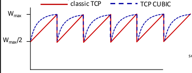
- is the window size at which congestion was last noticed.
- Define as the time for which, after a loss the rate is to increase, eventually reaching
- The window grows as .
TCP Vegas
- Delay based
- is the minimum measured RTT.
Ideally, this should be the RTT for the congested path.
- The uncongested throughput is thus
- if the measured throughput is “very close” to un-congested throughput, then increase cwnd linearly .
- if measured throughput is lower, decrease cwnd linearly
- This method maximises throughput
- Doing the same thing but with delays instead of rates maximised good-put rather than throughput.
- This is a very submissive algorithm. Aggression by other flows will cause it to decrease the
cwndlinearly, thereby giving the competitors even more breathing space, which no initial exponential increase phase for re-calibration.
TCP BBR
- Rate based
- Estimates Bandwidth-Delay-Product using both RTT measurement (delay) and loss events
- Keeps the sending rate (not just
cwnd) equal to the rate of the bottleneck link, thus avoiding bursts and queuing.
- While loss events are used too, their effect on the sending rate is reduced, making TCP BBR aggressive since it doesn’t care about failures (losses) that much and doesn’t give the competitor flows any breathing space.
RED
- Random Early Drop is a type of Active Queue Management (AQM).
- Let be the current measured queue length.
- We maintain a EWMA as .
- Let and be constant thresholds.
For any ingress packet apply this algorithm :
- measure
- Compute
- if :
- queue the packet
- else if :
- Compute probability
- drop packet with probability
- else :
- drop packet
ECN
- Rather than dropping packets in RED, you can mark the packet so that its ACK from the reciever will signal the sender to slow down.
- To mark the packet, the last two bits in the ToS feild for the IP header are set to 1.
- The reciever then set the ECN flag to 1 in the TCP header for the ACK.
- The sender on getting the ACK will reduce the congestion window and set the CWR flag to 1 in the next segment.
- Discard RTO calculation for any duplicate ACKs
Window Scaling Option
The reciever window feild in TCP header is only 16 bits while the sequence and achknowlegement number as 32 bits, implying that a window size of bytes is theoretically allowed but only bytes can be reached using only the TCP header. So, we pass in a TCP option which tells how many bits to left-shift the reciever window feild value to get the actual reciever window
RFC 7323 forces window scaling to be 14 at max; not even 15, which would give max window size of .
Note that the theoretical “unambiguous maximum” is but that’s not what the RFC states for implementation reasons.
SACK
Every SACK has a
- left edge : starting seq. number of data being acknowledged beyond the cumulitative acknowledgement number
- right edge : next expected seq. number for chunk acknowledged
Congestion control tidbits
- No loss event changes the
nextseqnum. On any loss event, you only retrasmit the base packet. TCP events (recieving dup ACK, non dup ACK, etc.) may change the cwd.
Ifnextseqnum < base + cwdyou can transmit more on such an event; otherwise ifnextseqnum > base + cwndthen don’t do anything. This “over-commitment” is allowed.
- cwnd is not increased on dup. ACKs when in SS or CA
- TCP Tahoe does have fast retransmit (and a loss event corresponding to that) but no fast recovery
- No loss event changes the
MSL
- Even when window is lower than half the seq. number space, we can still have a packet “living” in the network for much longer than RTT and then reaching the reciever at which point it would cause data that is already delivered (by retransmitted packets) to now be delivered again but at the wrong time, when it shouldn’t be. This will also cause the packets with overlaping seq number range to not deliver data (which should be delivered) . Thus, we now have the wrong data at the receiving end.
- To prevent against this, we must have the wrap-around time to be longer than the MSL.
- But the actual MSL is a not a value that we can estimate. Its default value of 2 min is often an orders big over-estimate of what it actually is in the system.
- The “theoretical maximum” of gives NO theoretical guarantee of correct ordering and neither does keeping wraparound less than a hard coded MSL.
PAWS
Protection Against Wrapped Sequence numbers
To actually solve this issue, we can use the timestamp option. The timestamps are 32 bits and generated at granularity of 1ms which is much smaller than the wrap-around times with modern high speed networks.
TCP options
- SACK
- WS
- Timestamp (used in PAWS)
- TCP-NODELAY (disables Nagle’s solution)
Taking a break..